Oracle BPEL Subprocess

There are quite a few new features in Oracle BPEL 12c and here is one that I really like; the BPEL subprocess – a task/algorithm that is an association (not composition) of an activity/process.

The concept has been around for decades and it has featured in process diagrams and BPMN notation for quite a while, but there was no equivalent in program code.  Oracle has finally addressed this lacuna by releasing a feature in BPEL that closely approximates the design concept.  Please note that it is close but not identical in semantics; but that again is to be pedantic – pardon the pun!

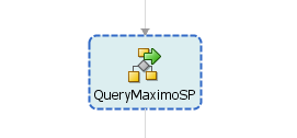
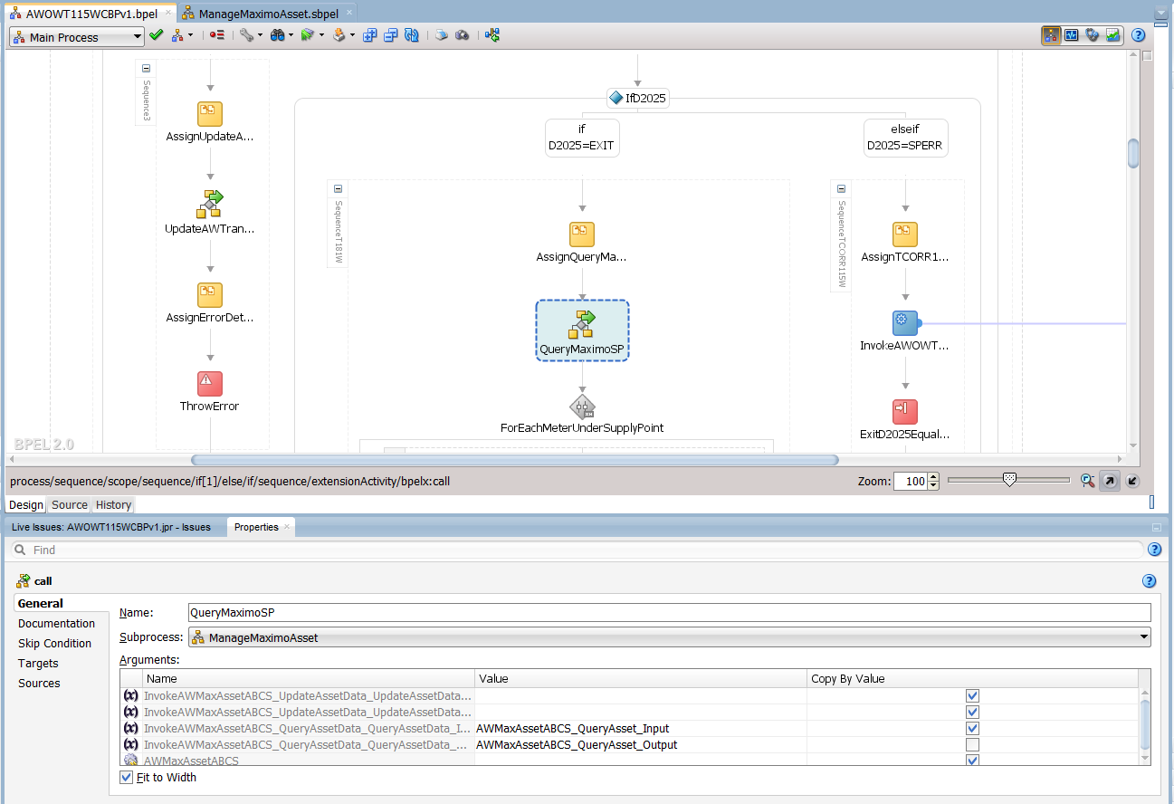
The subprocess allows a programmer to define a block of code or algorithm that will be reused as-is at various points within one or more BPEL processes.  I took the liberty of taking a few screenshots of active code from a recent client in order to illustrate a subprocess in action.  Before diving in though, it is useful to set the context.  The subprocess is being used in this scenario to wrap the invocation of operations on a service, and the task is named here as “QueryMaximoSP” – see highlighted item in the diagram below.

Call to the subprocess from the parent process

sub-process
sub-process icon
sub-process assignment


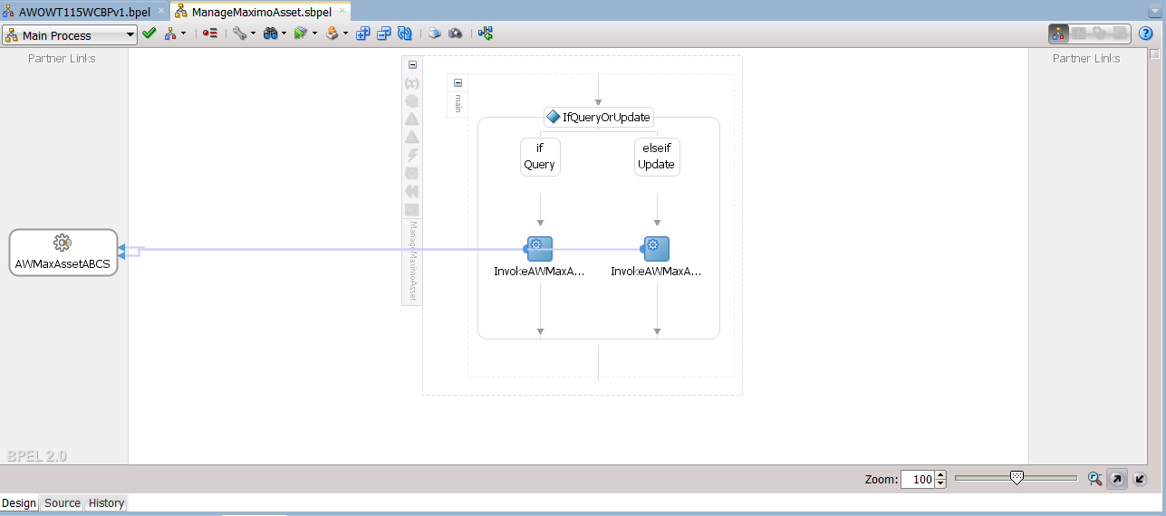
This subprocess wraps all the operations on the AWMaxAssetABCS service, and can determine which one is to be invoked by examining the inputs it receives from a main process.  In this simple example, the choice is implemented as if/else paths for “query” and “update” operations.  Once the operation has been determined invocation of the target service follows, using the input that was passed in by the main process.

Subprocess internal details

sub-process detail

There are three benefits that this concept brings to BPEL code:

  • Simplification of design view
  • Improved reusability
  • Improved modularisation

In the design view, hiving off some code into a subprocess frees up the screen from clutter and makes it much easier to see the big picture of what we are doing in the main process.  But what becomes of all this delegated code in production systems?  One fear may be that the subprocess will be displayed as a black-box.  This is not the case, all steps in the subprocess will be revealed at runtime, but only if they are executed.

Modularisation is improved because programmers can delegate as much logic to the subprocess as needed, including specialised error-handling and rollback, pre/post processing, and other conditional processing.  All of this functionality is thereafter available to all processes within a SOA composite, and each can invoke (reuse) the same subprocess multiple times with different inputs.

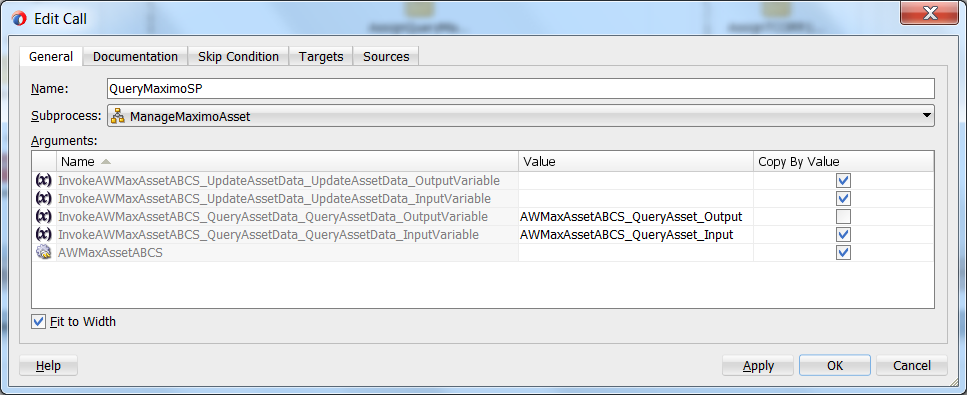
In the diagram below, input has been provided for the query operation while the update operation has been left blank, and so only the query operation will be acted upon in the subprocess.  Notice also that the “Copy By Value” checkbox of the output variable has been left unchecked.  This is important, as the invocation is likely to fail on the output variable if the checkbox is checked.

sub-process assignment

I have found it really useful to encapsulate the invocations to partner services in subprocesses, so that I can control all necessary pre and post processing in one place, as well as any necessary error handling and recovery that is specific to that partner system.  In future, it would be nice to have subprocesses that more closely resemble the concept in process models, i.e. a unit of functionality that can be reused across the domain, not just within one composite.  Now, some would argue that we should create a new composite to encapsulate the required functionality, but of course that would not be the same thing as in the model, and such a construct would also be significantly slower, not to mention that it would not fit nicely into a service portfolio.  Let’s wait and see if Oracle will be tweaking this feature in the next release of the JDeveloper and SOA Suite; for now though, there are already some great benefits realised in subprocesses.  I hope you find it useful too.

Regards and God bless.


Oyewole, Olanrewaju J (Mr.)
Internet Technologies Ltd.
lanre@net-technologies.com
www.net-technologies.com
Mobile: +44 [0] 793 920 3120

SOA Services Abstraction

There are many ways to conceptualise SOA services within an enterprise, and there are many ways to organise the implementation units. Here is an illustration of the SOA services architecture of a recent client. I think it is a tidy model, but as in my recent post on governance, “Rhema Bytes: Governance a Rope that Holds Development to Architecture?”, one must bear in mind that a model is only as good as its implementation. Furthermore, every model needs evolution and in the medium term, managing constructive change can be difficult, or disastrous. The devil is in the detail.

What is described here is a high-level view of a canonicalisation context, and it is very similar to Oracle’s AIA. The basic idea is simple. Having disparate clients and partners, a business needs to expose a platform of services, with the minimal set of technologies, components and patterns. The aim is to deliver the fewest generic patterns required to manage the boundary, and the implementation of internal functions. Whatever the design or model, every day use will throw up issues that require consideration. Not everything will fit any model. There will be calls for a dispensation for non-compliance, temporary exemption and technical debt; or changes to the model where inadequacies or incongruences are discovered.

It is useful to reference the post, “Rhema Bytes: The Business to SOA Nexus”, where the discussion was on core services that a business offers, and the automated processes that realise those services. To recap, the post identified business processes as a key focus of IT, and their implementation as the automation of business services. These automated business processes (BP) are the primary targets for the clients of the eBusiness. Most other services will normally be subsumed within the lifecycle of these business processes – with some exceptions. The BP is at the top level of the abstraction model under discussion here.

The diagram below provides an overview, with some AIA mappings:
SOA Zones with AIA Mappings

The genres of service shown in the diagram are described below:
BP – Business Processes (composite, long-running, process-centric, use cases)
Facilitates integration with core services and business, but is never accessed directly
Groupings: Process, Utility
AIA Equivalent: CBP, EBF
GS – Generic Services (composite or atomic, use cases)
Primary path into the enterprise for partners and integrators
This is an intermediation layer that decouples the enterprise from external systems
Types: Atomic, Composite
Groupings: Process, Data, Utility
AIA Equivalent: EBS, EBF
PS – Primitive Services (atomic use cases)
The only route outwards from enterprise
Secondary path into the enterprise – in addition to the GS
Types: Wrapper (BP), Adapter (GS), Mediator (partners), Facade (internal apps)
Groupings: Process, Data, Utility
AIA Equivalent: ABCS

BPs are the typical target for end users, especially human clients. However, there are exceptions, e.g. utility services, where a simple or business-agnostic use case delivers some value. Another example is for system integrators that compose existing services into new mashups. In such scenarios, it would be superfluous to add the overhead of a process. A BP must not be directly accessed by a partner. That would represent an unacceptable level of coupling between the enterprise and partner systems. Instead, BPs are accessed through an intermediary service; the details of that kind will follow in short order.

Partners that are involved in the value/supply chain may find it expedient to integrate directly with lower level services. In this case, the generic services (GS). This à la carte access is a complement to the prix fixe integration at the BP layer that is available to B2C and other clients. This option is of particular benefit where there are incongruences between internal order of tasks in equivalent processes.

Generic services (GS) are the default intermediation layer. GSs aggregate lower level services into functional components (data/process/utility), and serve as a facade for all underlying service units. GSs stand between the enterprise and partner systems and also decouple services internally. A GS will provide services to BPs and peer GSs from other groupings. A GS can be atomic or composite, depending on the number of lower level services that are involved in its value chain.

At the lowest level are the primitive services (PS). These are the gateway to the outside world. There is only one way out for requests emanating from the enterprise, and that is through the PS. The PS is the canonicalisation frontier for the enterprise; all, or most, mediation occurs here, be it data, protocol, security, transport, etc. Like the ABCS in AIA, PSs will convert from an application-specific schema to the canonical schema using custom EBM/EBO equivalents. The PS is also similar to the ABCS in that it normally routes requests to other services through the GS above it.

Partner (client) systems do not normally integrate inwards via a PS. Instead requests should are routed to the canonical GS layer. In most cases, this rule is good, but there are exceptions, due to significant differences between the types of PSs:
PSM – the default; this is a general purpose mediator to a partner system
PSF – a facade; this is wrapper around an internally developed application
PSA – an adapter; this facilitates a partner to access a service in a non-standard way
PSW – a wrapper; this simply puts a thin, non-active, decoupling layer over a BP

While the great majority of integration scenarios will be covered by the PSM variant, the other three break the rule. Either because they introduce a secondary PS layer (PS-to-PS) or that they facilitate access to the enterprise directly – (PS-to-BP), (PS-to-App).

SOA Services Abstraction Sequence Diagram - Requester

The model is similar to Oracle’s AIA, but there are a few differences. Incoming requests go through a generic interface, rather than an application-specific interface, as this cuts down the number of services – see exceptions above. Also, a request to a BP only goes through canonicalisation in a PS before it is directly passed on to the BP. Another difference is in the schema design; this model uses lightweight, flatter EBOs and very strict EBMs that constrain data domains. The end result though is the same, although each approach has its strengths and weaknesses.

SOA Services Abstraction Sequence Diagram - Provider

These service genres have clear functions which are not elaborated here, and there are preferred technologies for realising each one. The characteristics of the interface of each genre and the interaction patterns between genres are also largely predetermined.

In another article, “Rhema Bytes: A Factory Approach to Service Engineering”, the velocity and efficiency gains of automation is examined. This model is useful as a basis for creating templates or a factory for concrete building blocks. Each template is preconfigured with defaults for all the functional aspects of its type/class, and can be easily configured by developers to fit specific use cases. This has great value, especially for dispersed teams; it gets the horse to the river, quickly and easily. Of course the next challenge is to get it to drink 🙂 But that is a tale for another day!


Oyewole, Olanrewaju J (Mr.)
Internet Technologies Ltd.
lanre@net-technologies.com
www.net-technologies.com
Mobile: +44 [0] 793 920 3120

Simple Canonical Schema For Maturing SOA

In a previous article (Custom XSD Schema…) I examined the options open to the information architect when deciding on the adoption of XSD schema for SOA service messaging, and whether to choose an industry/community standard or go for a bespoke design that is tailored for the organisation at the point in time.

In this article, I present an overview of a custom messaging model (WSDL and XSD) that should work well for many small to medium sized IS/IT departments (10-200), especially where the information architecture function is either small or non-existent.  This model is therefore more than the canonical schema, but the minimal overhead in WSDL is necessary to create an end-to-end view of the service contract that is properly aligned.  So, to cut to the chase; let us start with an overview of the message model in the form of a diagram:

MessageModelLayers
Message Model Layers

This message model is like one of those nice layered cakes that you get at birthday parties, each layer has a different flavour and character, and the higher layers sit on, and depend on the lower layers.  Similarly, this model is built bottom up; each layer has a purpose and flavour that the layers above it depend/build on.

The Proper Canon: Base, CV and Complex:
At the lowest level, there are base types that constrain required XSD primitives into a few logical and physical domains.  The next layer contains the constrained value lists (enumerations), which are all constrained to one of the physical domains in the base types, and from that, define permissible values for certain static values for a generic type.

This layer introduces a peculiarity; “Infrastructure…”.  This construct is adopted for one purpose, to distinguish all non-business concepts.  In all the subsequent layers, any unit with “Infrastructure” in its name is concerned with IS/IT concepts rather than the core business.  Above the constrained values are the complex structures: these are common compound nodes with one or more child nodes/elements.  These three layers form our proper canonical schema, in that, everything in these three layers will be used as-is by all services in the enterprise.  Above this layer, we encounter a virtual layer, and then a service layer, and in these and other layers, perspective is everything; there is no single view of the world!

The Virtual Domains:
This is the virtual canonical schema.  The layer defines the template, or canonical form of all business and non-business (Infrastructure) concepts; the focus of this layer is coverage and correctness of definition and description rather than implementation, and this could be the bridge to an information model at some time.  Peculiar to this layer is the absence of constraints on the cardinality of data items; this is deliberate.  The absence of cardinality constraints makes it possible to defer this till later when development is imminent and allow all SOA services the liberty to define how the data will be used in their context.  The only proviso being that the structure and relationships of the data may not be augmented in any way, i.e. no moving, renaming, adding of nodes or relationships.

The Service Schema:
This layer becomes pertinent when implementation is about to begin; and the focus is in customising data structures from the virtual canon for specific use in the request and response of operations of services that use XML.  Much like the CV, Complex, Service, and Virtual layers, the service layer has business and “Infrastructure” units, but both have exactly the same function: to customise data from the virtual canon.  The service schema however needs to import the service infrastructure schema, since it is assumed that most services will be business focused rather than IS/IT focused, but the relationship could also be inverted in some scenarios.  For example, the data needed for CRUD (Create, Read, Update, Delete) operations will be different, and so it is useful that the interface of the Read operation is not cluttered with data that is only relevant for the Create operation.  The service schema could therefore specify only the ID of an Address for the input to the Read operation, whereas the Create will certainly not have an ID, but would need almost everything else: HouseName, HouseNumber, StreetName, PostCode, etc.

Service WSDLs:
The icing is put on the cake by the way of the service WSDLs (abstract and concrete).  This layer is included in the model to illustrate patterns that can be used to connect the data for the operations in the XSD to the operation definitions in the WSDL, and to support the premise that automation is not only plausible, but that auto-generation of service interfaces is on the radar.  For clarification; the abstract WSDL imports the service schema and is concerned only with the data structures that are needed by a service; the concrete WSDL on the other hand defines the implementation details of the service, i.e. what structures are needed for clients to access the service at runtime.

I hope this first piece has been useful; in the next installment I will build on this by introducing a new layer that will build on this foundation: Namespaces.

Ad Majorem Dei Gloriam.


Oyewole, Olanrewaju J (Mr.)
Internet Technologies Ltd.
lanre@net-technologies.com
www.net-technologies.com
Mobile: +44 [0] 793 920 3120