
Background
Security in an interconnected, always-on (24*7), virtualised, digital world is important. As more of our IT infrastructure moves to the Cloud, proactively seeking and blocking emerging security gaps becomes a continuous activity (BAU).
AWS and Kubernetes are leaders in the new paradigm of abstracted infrastructure – Cloud, datacentre on on-premise. Both have their own evolving security arrangements. For role-based access control (RBAC), AWS uses the IAM primarily, while Kubernetes (K8s) uses a combination of Roles and Role Bindings. The primary RBAC intersection point between these two has been the node/virtual-machine (EC2).
The Problem
In a simple world, privileges assigned to the underlying AWS node are inherited by the K8s Pods running on the node. This works perfectly when there is a one-to-one mapping between the client of K8s and the consumer of the AWS node. Specifically; the same entity owns the K8s cluster and the AWS node on which it runs. Security is intact, irrespective of the number of K8s Pods on the AWS node. However, misalignment occurs when K8s shares the same node among two or more clients – often referred to as multi-tenant mode. A potential for a security breach emerges.
Imagine a scenario in which there are three K8s Pods (A, B & C) running on a single AWS node. Each Pod runs a service that belongs to a different customer/client. Pod A belongs to client-A, Pod B belongs to client-B and Pod-C belongs to client-C. Files needed by each client are stored on S3 buckets in AWS, and each client has responsibility to arrange for their own S3 bucket. However, client-C is the only one that has managed to provision an S3 bucket at the time of deployment. Ordinarily, Pod A and B should never access the resource(s) provided strictly for Pod C. But if they do, nothing stops them! The diagram below provides a useful illustration.
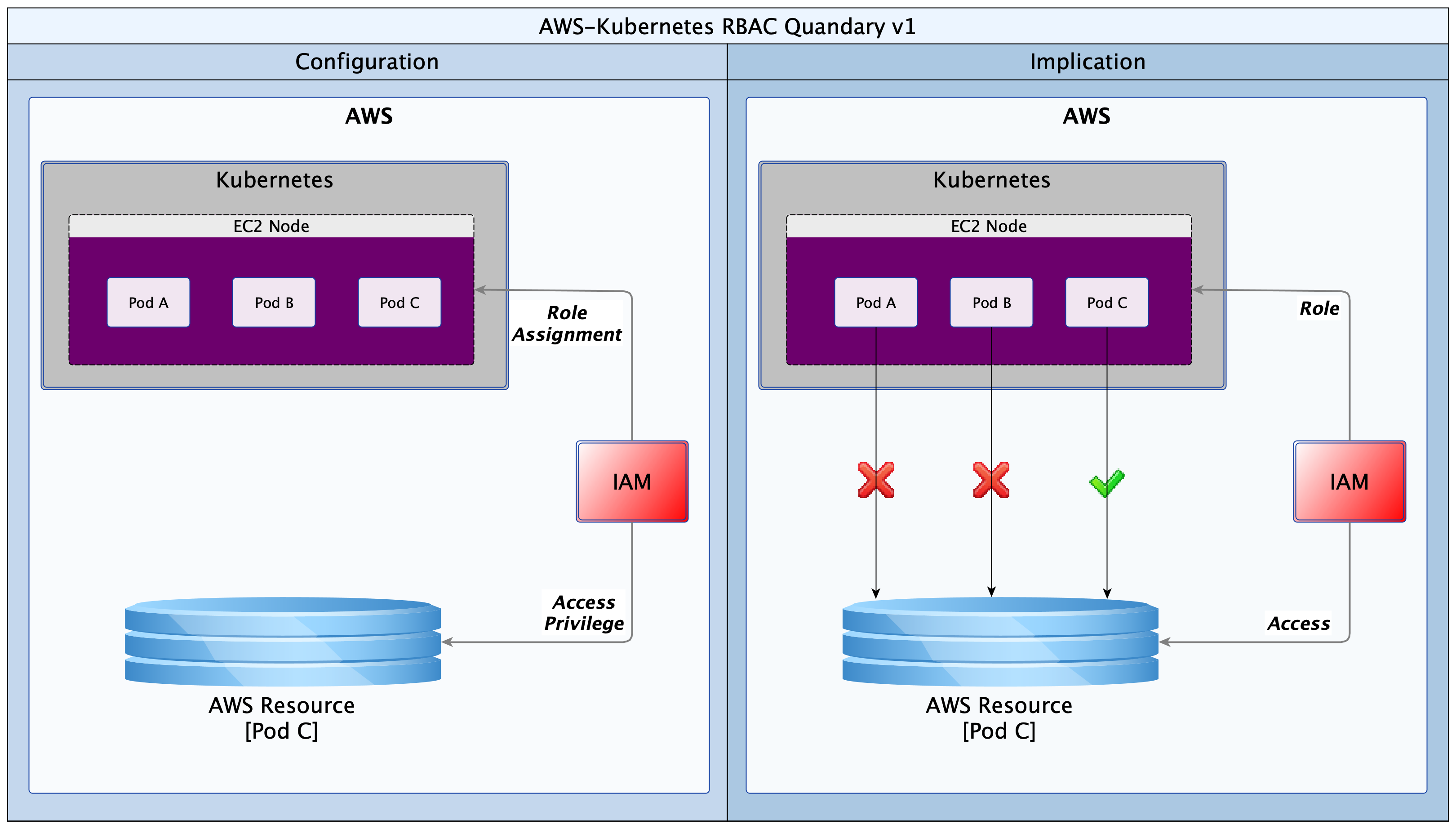
Historically, in IAM, access privileges to the resource for Pod C will have been given to the node hosting Pods A, B and C. The EC2 node would have an Instance Profile defined, and a Role will be attached to the Instance Profile, giving it those privileges. The unexpected consequence however is that Pods A and B also inherit the privilege from the host node. Pod C’s resources would therefore be accessible to any other Pod (client) running on that node. This obviously is not acceptable for a multi-tenant K8s cluster.
Solutions
The great thing about the Open Source community is that problems are attacked, and often solved, almost as soon as they are articulated. Two open source products emerged to close this security gap: Kube2IAM (2016) and KIAM (2017). Some time later, AWS introduced a solution; “IAM for Service Accounts”. However, the AWS solution only works with their EKS service. All three solutions make it possible to control access from K8s Pods to AWS resources.
I will not discuss the AWS solution as it is proprietary and closely tied to their EKS offering. Neither will I examine KIAM as the solution has been abandoned by the developers. This leaves us with the forerunner: Kube2IAM. Kube2IAM deploys a K8s DaemonSet in the K8s cluster. By default, one Kube2IAM Pod is deployed to each worker node in the cluster. The Kube2IAM instance running on each node intercepts requests to the AWS metadata service URL (http://169.254.169.254). It then provides a response according the the IAM role assignments, as well as the annotations on the Pod calling the service. The diagram below provides a useful illustration.
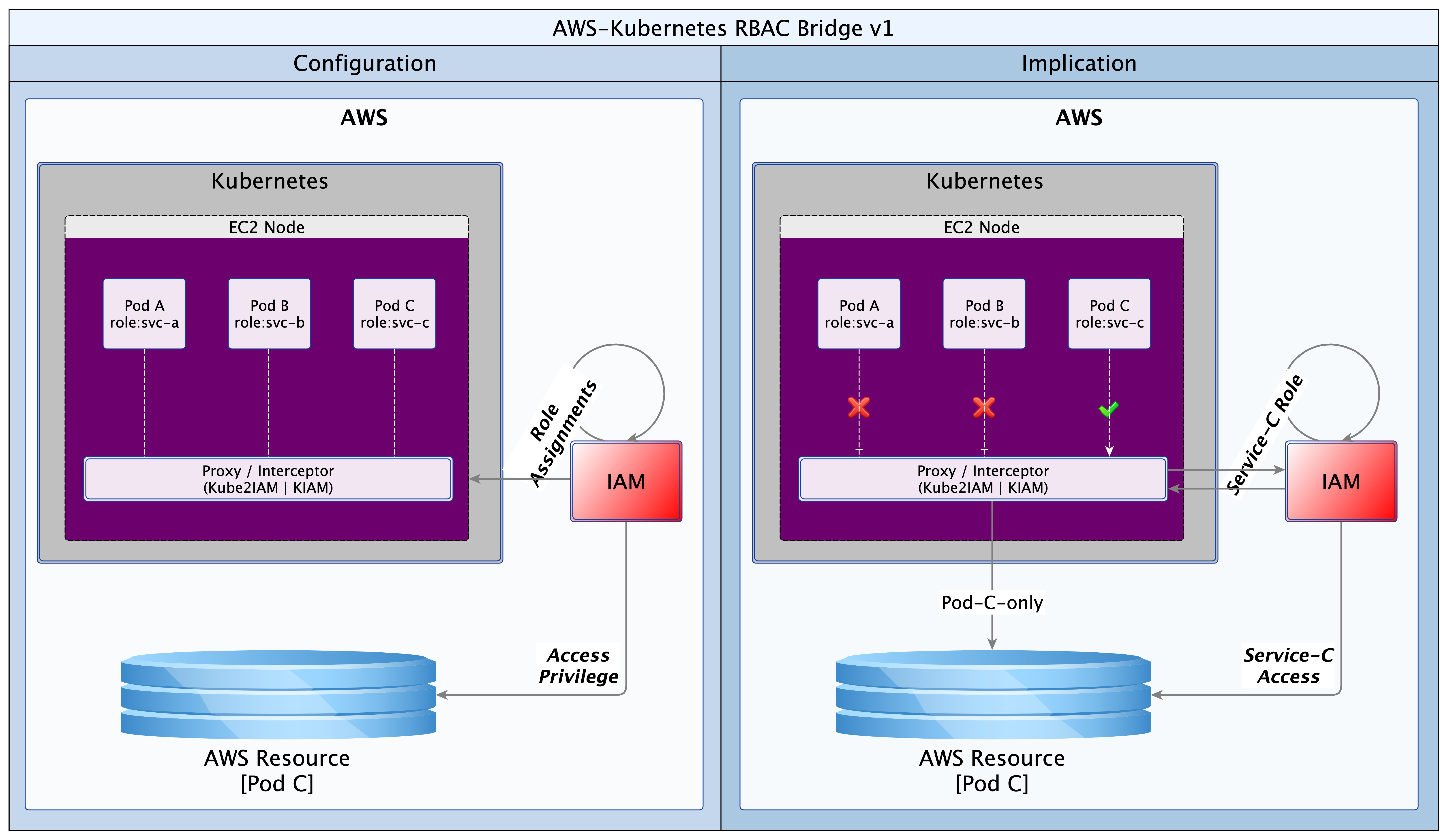
With this simple solution by Kube2IAM, the exclusive role assignment to Pod C is respected by K8s. Deliberate or inadvertent requests by Pod A or B are blocked by Kube2IAM.
Here is how it works. When a Pod makes a request for AWS resources, it will make a call to the AWS metadata service URL. Kube2IAM hijacks the call (iptables reroute) and performs an inspection to see what the appropriate response should be. It checks if there are any appropriate RBAC annotations on the Pod making the request. If there are none, Kube2IAM serves up the default privilege set. These will be the privileges defined for the EC2 Instance Profile. However, if the Pod has a role annotation, it will be given the privileges defined in the matching AWS role.
Hands-on
In the example that follows, we will deploy two Pods; one with annotations (annotated) and another without (vanilla). We will use two AWS roles. The read-only role will have access to one S3 bucket only. The other read+write role will have read access to 2 buckets and read+write access to one bucket. The read-only role will be attached to the EC2 Instance Profile for the K8s worker node. The read+write role be standalone, but it will be extended to trust the read-only role. This sets the stage for Kube2IAM to discriminate between requests, giving read and/or write access to our Pods, as appropriate. In our example, the annotated Pod will be able to write one bucket and read two buckets, while the vanilla Pod will only be able to read one bucket.
The implementation artefacts can be downloaded from GitHub (use this link). I have put together what I think is a simple, and perhaps more explicit set of instructions below. Follow them step-by-step and you should end up with a working RBAC bridge using Kube2IAM. I guess one could write a script that automates all of these steps, but that is a task for another day, or perhaps someone else.
Process
- Create a policy (nettech-s3-read-only); use the file nettech-ec2-instance-profile.json for the policy definition/contents
- Create a role (nettech-s3-read-only); the role should refer to the policy in step #1
- Create an EC2 instance profile (nettech-instance-profile) for the AWS node(s); the instance profile should refer to the role you defined in step #2, forming a chain:
nettech-instance-profile==>nettech-s3-read-only(role)==>nettech-s3-read-only(policy).-
Use the following aws-cli commands:
aws iam create-instance-profile –instance-profile-name nettech-instance-profile
aws iam add-role-to-instance-profile –instance-profile-name nettech-instance-profile –role-name nettech-s3-read-only - Create a second read+write S3 policy and role (nettech-s3-read-write). Use the file nettech-s3-read-write.json for the policy definition/contents
- Extend the trust relationship on the read+write S3 role such that it can be assumed by the read-only role, forming a link:
nettech-s3-read-write(role)<==trust==nettech-s3-read-only(role).-
In IAM console, select the read+write role
Select the “Trust relationships” tab, and then click on the “Edit trust relationships” button
In the new window that opens, add the contents of the file nettech-s3-read-write-trust-relationship.json to the existing definition/contents
Make sure to update the AWS account Id (01234567890) to your own
Click on “Update Trust Policy” to save your changes - Deploy or assign a worker node in your K8s (Rancher/Kops/..) cluster
- Configure or update the worker node to reference the EC2 Instance Profile (nettech-instance-profile) from step #3
-
aws ec2 associate-iam-instance-profile –iam-instance-profile nettech-instance-profile –instance-id xxxxxxxxxx # replace xxxx with your instance Id, or use the AWS GUI to attach it
- Deploy Nginx vanilla and annotated (K8s Deployments). Use the file nginx-deployment.yaml from Rancher UI or kubectl on the command line
- Install aws-cli in each of the Nginx instances – Use the following commands (Linux):
-
apt update
apt install curl -y
apt install unzip -y
curl "https://awscli.amazonaws.com/awscli-exe-linux-x86_64.zip" -o "awscliv2.zip"
unzip ./awscliv2.zip
./aws/install - Verify that the host node has read access to the “nettech-helm-test” bucket, according to the EC2 profile from step #3. Connect to the host node (via Rancher UI or SSH) and run the aws s3 ls command.
-
aws s3 ls nettech-helm-test
- Verify that both Pods have read access to the “nettech-helm-test” bucket. Connect to each Pod (via Rancher UI or kubectl) and run an aws s3 ls
-
aws s3 ls nettech-helm-test
- Create/deploy ClusterRole & ClusterRoleBinding for the service account to be used by Kube2IAM. Use the file clusterRoleAndBinding.yaml
- Deploy Kube2IAM (K8s DaemonSet), with debugging enabled. Use the file kube2IAM-daemonSet.yaml
- Connect to the host node and access the command line. Check that only one IPTables rule exists on the worker node (for AWS metadata IP). Delete any duplicates to avoid confusing errors. This may happen if you redeploy the Kube2IAM Daemonset.
-
sudo iptables -t nat -S PREROUTING | grep 169.254.169.254 # list all entries
sudo iptables -t nat -D PREROUTING -d 169.254.169.254/32 -i docker0 -p tcp -m tcp –dport 80 -j DNAT –to-destination 10.43.0.1:8282 # delete any duplicates
NB: (docker0) is the network interface, (10.43.0.1) is the IP address of the node/host, and (8282) is the Kube2IAM port - Test the Nginx instances again
- Verify that the host node still only has read access to “nettech-helm-test”, as defined as a default in the EC2 Profile role (nettech-s3-read-only)
- Verify that the vanilla Nginx Deployment still only has read access to “nettech-helm-test”, as defined as a default in the EC2 Profile role (nettech-s3-read-only)
- Verify that the annotated Nginx Deployment now has read access to “lanre.k8s.dev” and “nettech-helm-test” as well as read+write access to “lanre.k8s.dev”
Conclusion
An RBAC bridge of some sort is a necessity for all multi-tenant K8s clusters running on virtualised infrastructure such as AWS, Azure, GCP and others. Kube2IAM provides an effective solution for the AWS platform. This article identifies the issue that Kube2IAM resolves and shows a very simple, sandbox implementation. The article should serve as quick-start guide that is easy to grasp and quick to implement.
We live in a rapidly evolving technology environment. Kube2IAM has set a very sound foundation, but as always, there is always room for improvement; and I say that with all humility and respect for the developers. KIAM came up with a cacheing service to reduce latency and improve scalability, unfortunately, that solution is no longer being evolved. One would like to see similar functionality in Kube2IAM. One other improvement would be to move the annotations out of the Pod and into K8s roles. The preference being roles defined outside the namespace of the beneficiary Pod. This will reduce the attack surface for malicious code that might attempt a brute-force attack to find AWS roles that can be exploited.
Many thanks to Jerome Touffe-Blin @jtblin and his team for creating this ever-so-useful open-souce utility.
—
Oyewole, Olanrewaju J (Mr.)
Internet Technologies Ltd.
lanre@net-technologies.com
www.net-technologies.com
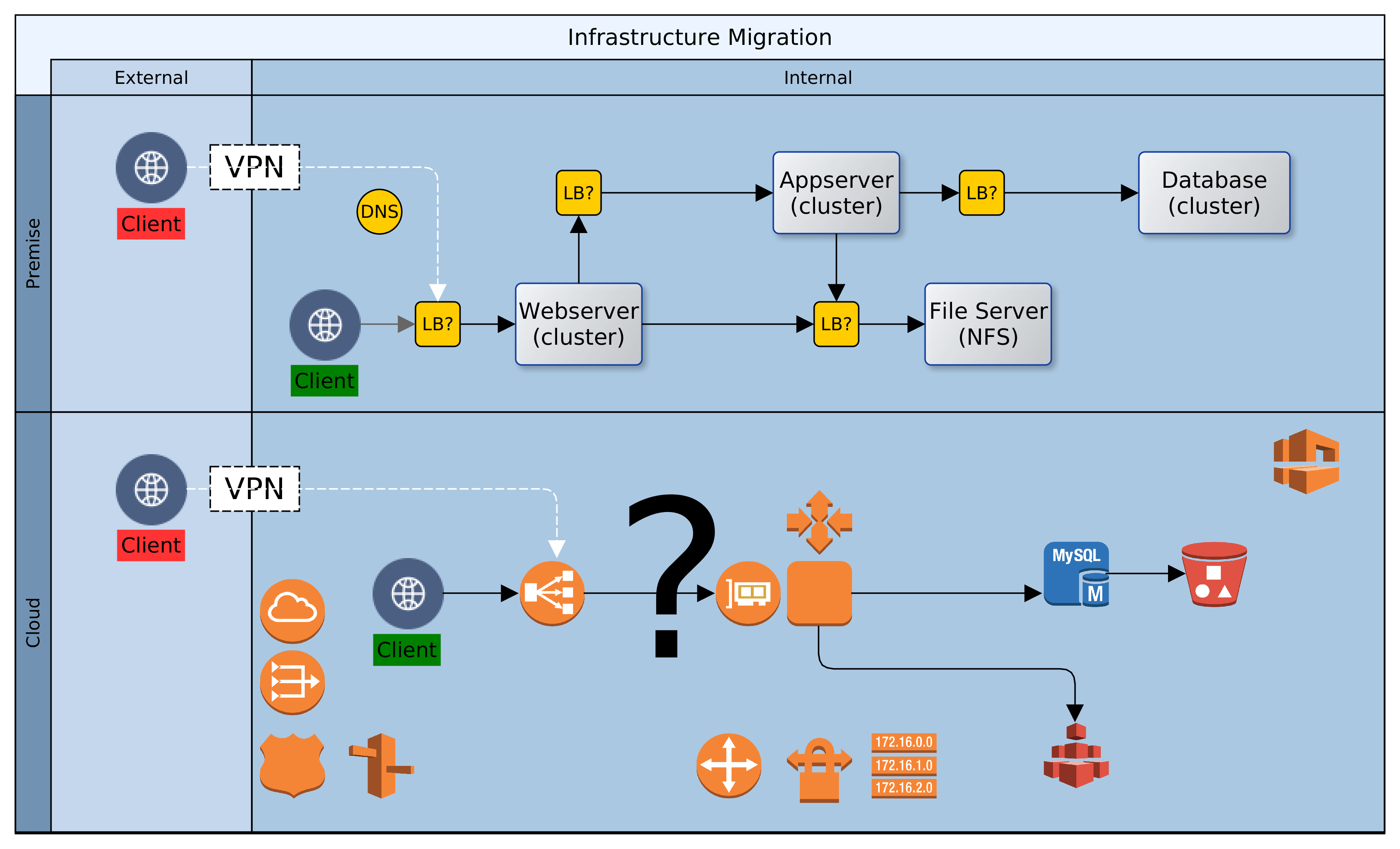

![[Hybrid] Cloud Infrastructure](https://blog.net-technologies.com/wp-content/uploads/2017/12/ExeterUni_CloudInfrastructure.03.png)
![[Hybrid] Cloud Infrastructure](http://blog.net-technologies.com/wp-content/uploads/2017/12/ExeterUni_CloudInfrastructure.03.png)