Simple Canonical Schema For Maturing SOA

In a previous article (Custom XSD Schema…) I examined the options open to the information architect when deciding on the adoption of XSD schema for SOA service messaging, and whether to choose an industry/community standard or go for a bespoke design that is tailored for the organisation at the point in time.

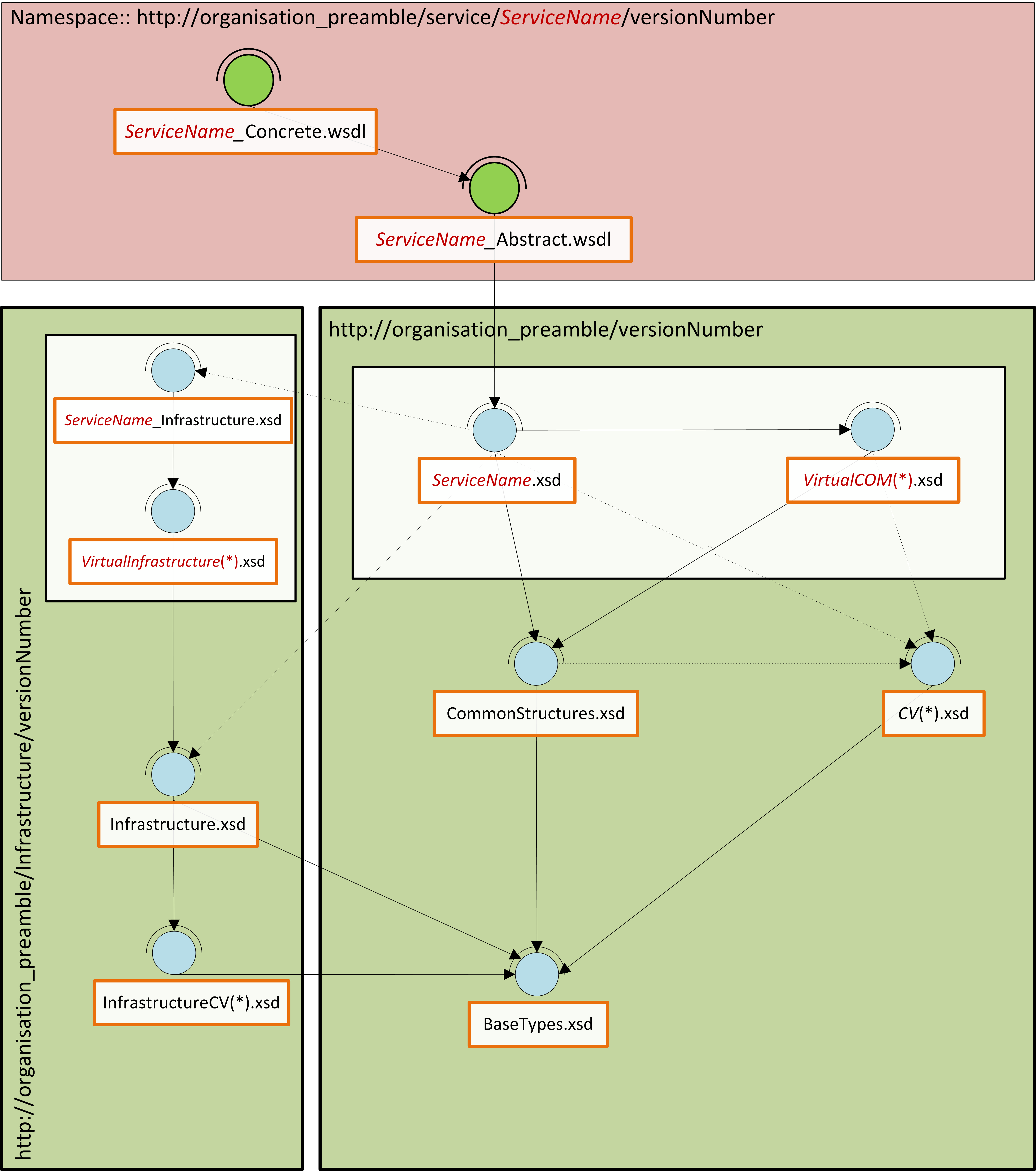
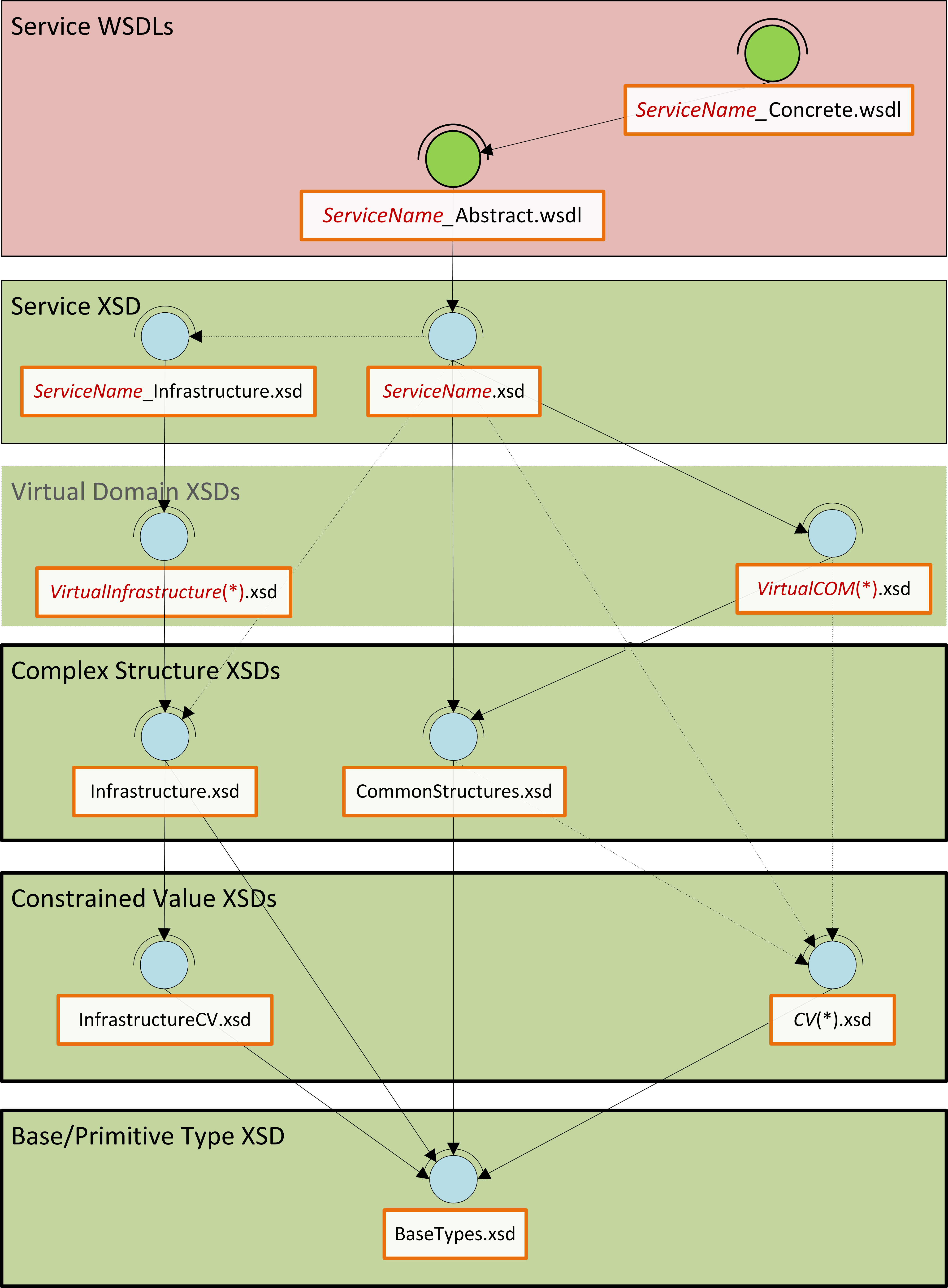
In this article, I present an overview of a custom messaging model (WSDL and XSD) that should work well for many small to medium sized IS/IT departments (10-200), especially where the information architecture function is either small or non-existent.  This model is therefore more than the canonical schema, but the minimal overhead in WSDL is necessary to create an end-to-end view of the service contract that is properly aligned.  So, to cut to the chase; let us start with an overview of the message model in the form of a diagram:

MessageModelLayers
Message Model Layers

This message model is like one of those nice layered cakes that you get at birthday parties, each layer has a different flavour and character, and the higher layers sit on, and depend on the lower layers.  Similarly, this model is built bottom up; each layer has a purpose and flavour that the layers above it depend/build on.

The Proper Canon: Base, CV and Complex:
At the lowest level, there are base types that constrain required XSD primitives into a few logical and physical domains.  The next layer contains the constrained value lists (enumerations), which are all constrained to one of the physical domains in the base types, and from that, define permissible values for certain static values for a generic type.

This layer introduces a peculiarity; “Infrastructure…”.  This construct is adopted for one purpose, to distinguish all non-business concepts.  In all the subsequent layers, any unit with “Infrastructure” in its name is concerned with IS/IT concepts rather than the core business.  Above the constrained values are the complex structures: these are common compound nodes with one or more child nodes/elements.  These three layers form our proper canonical schema, in that, everything in these three layers will be used as-is by all services in the enterprise.  Above this layer, we encounter a virtual layer, and then a service layer, and in these and other layers, perspective is everything; there is no single view of the world!

The Virtual Domains:
This is the virtual canonical schema.  The layer defines the template, or canonical form of all business and non-business (Infrastructure) concepts; the focus of this layer is coverage and correctness of definition and description rather than implementation, and this could be the bridge to an information model at some time.  Peculiar to this layer is the absence of constraints on the cardinality of data items; this is deliberate.  The absence of cardinality constraints makes it possible to defer this till later when development is imminent and allow all SOA services the liberty to define how the data will be used in their context.  The only proviso being that the structure and relationships of the data may not be augmented in any way, i.e. no moving, renaming, adding of nodes or relationships.

The Service Schema:
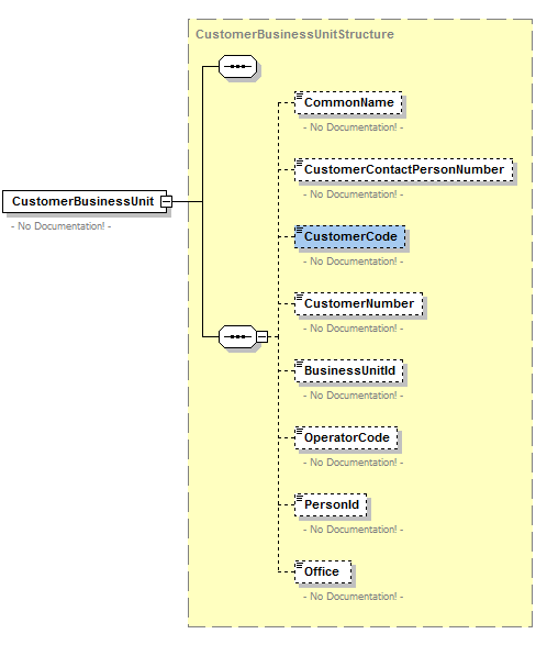
This layer becomes pertinent when implementation is about to begin; and the focus is in customising data structures from the virtual canon for specific use in the request and response of operations of services that use XML.  Much like the CV, Complex, Service, and Virtual layers, the service layer has business and “Infrastructure” units, but both have exactly the same function: to customise data from the virtual canon.  The service schema however needs to import the service infrastructure schema, since it is assumed that most services will be business focused rather than IS/IT focused, but the relationship could also be inverted in some scenarios.  For example, the data needed for CRUD (Create, Read, Update, Delete) operations will be different, and so it is useful that the interface of the Read operation is not cluttered with data that is only relevant for the Create operation.  The service schema could therefore specify only the ID of an Address for the input to the Read operation, whereas the Create will certainly not have an ID, but would need almost everything else: HouseName, HouseNumber, StreetName, PostCode, etc.

Service WSDLs:
The icing is put on the cake by the way of the service WSDLs (abstract and concrete).  This layer is included in the model to illustrate patterns that can be used to connect the data for the operations in the XSD to the operation definitions in the WSDL, and to support the premise that automation is not only plausible, but that auto-generation of service interfaces is on the radar.  For clarification; the abstract WSDL imports the service schema and is concerned only with the data structures that are needed by a service; the concrete WSDL on the other hand defines the implementation details of the service, i.e. what structures are needed for clients to access the service at runtime.

I hope this first piece has been useful; in the next installment I will build on this by introducing a new layer that will build on this foundation: Namespaces.

Ad Majorem Dei Gloriam.


Oyewole, Olanrewaju J (Mr.)
Internet Technologies Ltd.
lanre@net-technologies.com
www.net-technologies.com
Mobile: +44 [0] 793 920 3120

XSD Schema Architecture

MessageModelNamespaces

This subject matter here is architecture of XSD schema for an enterprise SOA, and an important side-theme is the exploration of automation potential in this area. The content is quite detailed, and perhaps not best suited for viewing in a web page; therefore PDF and Micorsoft Word versions are provided in the links below:

XSD Schema Architecture (PDF)
XSD Schema Architecture (MS Word)

This is an “insight” post; it aims to stimulate discussion around the subject it discusses; these articles may appear prescriptive and perhaps dogmatic, but the objective really is for debate that leads to reusable knowledge and that is accessible to the wider community of software engineers in the area of focus.

Please be aware that the content of the document is the output of work done in one SOA adoption context. The majority of the design choices were driven by standards, known best practise and some original thinking, however, a few decisions and choices were informed by the context in which the solution was being articulated.
The authors have moved on from some of these positions, and so feedback and criticisms will be very much appreciated, in order that all may get wiser.
Many thanks in anticipation.


Oyewole, Olanrewaju J (Mr.)
Internet Technologies Ltd.
lanre@net-technologies.com
www.net-technologies.com
Mobile: +44 [0] 793 920 3120

ESB Service Meta Design

OSB Service Meta Design

This post explores the idea of a meta model for the design of services in an Enterprise Service Bus (ESB), by identifying key competencies that services should realise. While there are exceptions to every case, the majority of services will find the realisation of these core competencies beneficial.

This is an “insight” post; it aims to stimulate discussion around the subject it discusses; these articles may appear prescriptive and perhaps dogmatic, but the objective really is for debate that leads to reusable knowledge and that is accessible to the wider community of software engineers in the area of focus.

This however is a meta design, so there is no code or example to show, neither is it advised to translate this directly into an implementation, without empathy for the usage context.

In my mind the core competencies of any enterprise service bus can be expressed in the acronym (REM); these are:
1). Routing
2). Enrichment
3). Mediation*

It is the complement of these core competencies that distinguish the ESB from other technologies within a SOA stack, and no business should countenance purchasing an ESB implementation if it does not provide these core competencies. Now, these core competencies are foundational and key, but there is a need for other ancillary comptencies to make for a compelling service offering, which will be introduced later. So, starting from the core, let us peruse the competencies.

Routing:
Routing is all about delivery and making sure that requests are delivered to the target most likely to return value to the client of the enterprise; often, logic is required to implement routing intelligently, including dynamic destinations. Routing by the ESB decouples the client from the provider/implementation of the service, so that a change of service provider might be limited in impact to a change of the rule(s) or computation of routing.

Enrichment:
Enrichment, as the name implies is adding information to an incoming or outgoing message. The simple case is where simple/atomic data item(s) are added from the context, but in some cases, the required data may need to be sourced from other services, in which scenario, enrichment takes the form of service composition.

Mediation:
I have marked out the third competence, Mediation, because it really is a composite of: security, protocol, message-pattern, data-format, etc. Mediation is the bridging of difference between two clients of the ESB; to wit, the client, and the provider. It is comparable to standing between the Taliban and US forces 🙂 In any conversation, there will be many differences. Mediation aims to bridge the gap, despite the many dimensions of difference, it may take various forms in one message exchange, even where canonicalisation is widespread.

In an implementation context, the service bus will sit on the boundary of the SOA, be it departmental or enterprise, and would be expected to provide certain value-add to applications, sub-systems, and services within the boundary, among which are:
1). Auditing
2). Security
3). Validation
4). Error management

Auditing:
The ESB is the best place for auditing of access to services since it is the first port of call of “clients” (external, and in some cases internal as well), therefore it is the most convenient location for keeping tabs on service usage parameters. One strategy I have witnessed is to log key-identifiers for each request; this makes it easy to trace problems through the rest of the enterprise, using only WS-Addressing headers.

Security:
If the ESB is fully delegated to man the boundary of the enterprise, it makes sense to delegate a significant chunk of the respobsibility for security to this layer. It is also a lot easier to implement a system in which all requests inside the boundary provided by the ESB, are to be trusted. The ESB becomes the frontier between the green zone and the red zone, said frontier being within the zone already protected by Firewalls and other security infrastructure that operate at the organisational/infrastructure level. This role (authentication and authorisation) may be realised by the ESB itslef, or further delegated to another component/layer within the SOA stack.

Validation:
Many years ago, the acronym GIGO was quite popular; it is not often heard these days, but it is still relevant. Spelled out it means Garbage in, Garbage out. For the enterprise, Garbage in is bad news. It means valuable resource is being given over to service requests that will eventually return no value to the client. The deeper into the enterprise this junk travels, the more expensive it is to the business and its ability to scale and be available to valid requests. The ESB, should filter out bad data, just as it filters out bad guys, leaving other services free to focus on their core competencies.

Error Management:
The service bus is an intelligent, real-time post office that has visibility of most of the traffic moving in and out of the enterprise. For this reason, it is able to apprehend requests whose signature is known to provide no value to clients of the enterprise, and for which there is no known owner/manager. The ESB should therefore provide a problem-handler of last resort within the enterprise, so that such maligned messages are handled predictably and by the most likely target that can transform the problem into a solution or a relationship.

Design:
Having said much about the core and ancillary competences, it is pertinent at this juncture to return to our meta-design, and to say, all that has passed before is a buffet, wisdom though is needed to discern where desert ends and the main course begins, and whether to have the cheese and jam, after lamb, or to go for a coffee instead 🙂

Design must therefore weigh the value of all these comptencies in light of the context of use, and determine if there is value in implementing the competency in the ESB. For example, security must be examined in light of the value/confidentiality of messages, as well as the completeness of existing security provisions. Where existing facilities are adequate, or the value of the data in the messages is limited, security may or not be a value-add in the ESB; there are other considerations as well, such as performance costs of security for high demand services.

Where beneficial, the ESB service should facilitate auditing of all service requests to the enterprise, irrespecitive of the validity of said requests. Validation should be enforced as the next step for incoming messages, to ensure that the request conforms to the service contract, validation should also occur as one of the last tasks performed on outgoing messages, to ensure that the enterprise honours its contract with clients. Requests that fail validation must be prevented from going any further into the enterprise and an indicative response must be returned to the client.
Most ESB services will be required to undertake some mediation, especially if the service is at the boundary of the enterprise; such mediation will be one of the first step for incoming requests, and the one of the last steps for outgoing responses. Mediation will be influenced by the extent of canonicalisation and centralisation patterns in use in the enterprise, and the degree of overlap between the enterprise, partner systems in its value chain, and clients of the enterprise.

Enrichment is an optional task, the need for which may decrease with canonicalisation, and in scenarios where services are deployed as a wrapper, or for decoupling in one of the following scenarios: client to service provider; SOA layer to SOA layer. However, every ESB service must perform some kind of routing, because every request to the enterprise will have a destination. Most scenarios will be static, where the destination is pre-determined and unchanging; or static-calculated, where the full complement of possible destinations are known and unchanging. In exceptional cases, and in very sophisticated SOA, dynamic routing comes into play where the destination is rule-based, or a lookup, in these scenarios, the routing takes a form of service composition where another service (rule engine, or database) is relied upon to determine the destination of a request. Typically, routing will be the last step for an incoming request. It is useful to make a note on error management; this is an event that has no specific sequence of incidence, however each service implementation should provide this competence, even if it is delegated. In whatever form this implementation takes though, it is important that it does not interfere with the context, especially where transactions are involved.

To conclude, it is advised that for each competence, a value should be attached against the cost of SOA-wide implementation against localised implementations, and provisions of the same competence by other technologies in the SOA stack; a useful tool would be a matrix that lists each competency against alternative technologies, and for each, to identify the cost and value of a SOA-wide or localised implementation; notes should be appended for any context-related issues. The outcome of such an exercise will go a long way to help an organisation identify a meta-design for how best to use the various competencies of an ESB in the SOA, be it departmental or enterprise.
The flexibility, efficacy and efficiency of the configuration arrived from a meta-desing will determine the success of the ESB implementation and the services therein.


Oyewole, Olanrewaju J (Mr.)
Internet Technologies Ltd.
lanre@net-technologies.com
www.net-technologies.com
Mobile: +44 [0] 793 920 3120

Test Automation With Plain SoapUI

Test Automation mit SOAP UI

Automation Illustration

Have you ever wanted to run some features that are only available in SOAP UI Pro?
Well, a little grasp of Groovy scripting can help you to simulate some of those high-falutin features
that would have cost you $$$ per year in licenses.  Here is one neat feature that I really like.

Running All Projects in a Workspace

This feature is not available in the free (community version) of SOAP UI, but the Groovy script
described in this post will do the same thing, without hurting your wallet.

Here are the steps for using the project file in SOAP UI

  1. Open or create a new Workspace in SOAP UI
  2. Add/import all the projects you want to run into the workspace
  3. Import the test harness SOAP UI project.  You can download the project file from > here <
  4. Remove any projects that are to be excluded
  5. Expand the “ExecutionHarnessExample” project and run the only TestStep – Groovy script “RunProject”

The script will loop through all the test Projects, TestSuites, TestCases and TestSteps, while also printing a summary of the progress to screen, and where indicated, logging the complete test logs to a file.  The script prompts the user for the path to the log file.  Accepting the default value “DO-NOT-LOG”, turns off logging.

soapUIDoNotLog

Enter a valid path to enable logging.  The name of the log file is saved to a global property, so it is available even after the test run (in case you forget)

soapUILog

A useful feature of the script is that assertions are exercised, so you can see TestSteps turning green or red as they are being run!

soapUI2

The script is quite simple, and you can open it in SOAP UI for a detailed walk-through, but below are the salient things:

// Save the name of this automation project
//it will be needed later to prevent infinite looping
def executionProjectName = testRunner.testCase.testSuite.project.name// Get a handle on the SOAP UI workspace
def testWorkspace = testRunner.getTestCase().getTestSuite().getProject().getWorkspace();// Ask user to confirm if test output should be logged to default file
filePath = ui.prompt(…);// First, a loop is created for all the Projects in the in the SOAP UI Workspace
for (int projectCounter = 0; projectCounter < testWorkspace.getProjectCount(); projectCounter++) {// Exclude the automation project else you get an infinite loop!
if (testProject.name != executionProjectName) {// Exclude disabled TestSuites from the loop
for (… (!testProject.getTestSuiteAt(suiteCounter).isDisabled())); suiteCounter++) {// Create a TestRunner for running the TestSteps in this TestCase
testCaseRunner = new com.eviware.soapui.impl.wsdl.testcase.WsdlTestCaseRunner(testCase, null);// Run each TestStep in the TestCase
testStepResult = … testStep.run(testCaseRunner, testStepContext);// Log the output if requested
if ((filePath != null) && (filePath != ”) && (filePath != ‘DO-NOT-LOG’)) { testStepResult.writeTo(fileWriter); }// Close the output file when all Projects have been processed
fileWriter.close()


At the end of the test run, you can view the log file in a text editor like TextPad and view the messages exchanged (including headers) as well as timings.

soapUILogFile

And that’s all folks; I hope you found the posting useful.
It has certainly helped me put off the purchase of a SOAP UI licence for another day 🙂
God bless!


Oyewole, Olanrewaju J (Mr.)
Internet Technologies Ltd.
lanre@net-technologies.com
www.net-technologies.com
Mobile: +44 [0] 793 920 3120

Hands On: Installing SOA Suite on a Laptop

Installation Detail


Installing Oracle Tools on a Laptop [64-bit]


1). Install a Java 7 JDK – 64-bit version

Run the JDK installer file – jdk-7u21-windows-x64.exe


2). [optional] Install Oracle XE

There is no 64-bit Oracle XE for Windows, so 32-bit is the only option either way!

Expand the Oracle XE installer archive (OracleXE112_Win32.zip) into a folder – installHome

Start the Oracle XE installer file … installHome/DISK1/setup.exe


3). [optional] Install Oracle RCU into XE database

Expand the RCU zip file into its own directory – InstallHome

Start the RCU installation file … $InstallHome/rcuHome/BIN/rcu.bat

Untitled1

Fill in the details as above and click next.
An error message is displayed (see below); click on ignore

Untitled1


Select the schemas to be installed by the RCU utility – see checked boxes below

Untitled1


This should result in a successful pre-requisites check – see below.

Untitled1


In the next step, specify the same username/password for all the schemas – keep it simple

Untitled1


Use the same password on the next screen for the Supervisor and Work Repository password

Untitled1


Accept the defaults on the next screen and just click on “Next”; when prompted about creation of non-existent tablespaces, click “OK” and continue.  Click “OK” again after the tablespaces have been created.

Untitled1


The next screen that appears will show a summary of the users and tablespaces that have been created, and prompt to create the data/records in the database; accept and click “Create”.

Untitled1


Ignore any errors and run the patch script (rcuFix.sql) at the end of the installation.  The rcuFix.sql script contains the statements below:

ALTER SESSION SET CURRENT_SCHEMA = dev_epm;

CREATE VIEW “ESS_FAILOVER_ACTIVE_NODE_VIEW” AS SELECT R.CLUSTER_NAME, LEASE.HOST_NAME, LEASE.PORT_NUMBER, LEASE.SECURE_PORT_NUMBER FROM ESS_FAILOVER_RESOURCE R LEFT JOIN ( SELECT LO.PORT_NUMBER, LO.HOST_NAME, LO.SECURE_PORT_NUMBER, L.RESOURCE_ID from ESS_FAILOVER_LEASE_OWNER LO, ESS_FAILOVER_LEASE L WHERE LO.LEASE_OWNER_ID = L.LEASE_OWNER_ID AND SYSTIMESTAMP < L.EXPIRY_TIME ) LEASE ON R.RESOURCE_ID = LEASE.RESOURCE_ID WHERE R.RESOURCE_NAME=’essbase.sec’ ;

ALTER SESSION SET CURRENT_SCHEMA = sys;
GRANT EXECUTE ON utl_file TO dev_ess;
ALTER PROCEDURE dev_ess.write_line COMPILE;
SHOW ERRORS;


In the next window that opens, click on “Close”

Untitled1


4). Install Oracle OEPE into a new WebLogic home

Start the OEPE installer file – oepe-wls-???-installer-11.1.1.?.0……win32.exe

Accept or specify C:\Oracle\Middleware as the new Oracle home

Untitled1


Uncheck the box to receive security updates by email and click “Yes” when prompted to continue.  In the next window, select the “Custom” install option.

Untitled1


Ensure that the “Server Examples” box is checked (below)

Untitled1

Accept the default settings in all the windows that follow and proceed to the end of the installation.


5). Apply OSB extension to the WebLogic home

Expand the OSB extension archive – ofm_osb_generic_11.1.1.?.0_disk1_1of1.zip
Open a DOS window and navigate to installerHome/Disk1
Run the setup.exe file … setup.exe -jreLoc pathToJavaJREHome
In the window (2 of 9) that appears, choose to skip the check for Software Updates

Untitled1


In the next (3rd) window, choose the existing middleware home that was created for the OEPE install (C:\Oracle\Middleware) and select Oracle_OSB as the home directory, and click “Next”

Untitled1


In the next (4th) window, accept the default (Typical install) and click “Next”

Untitled1

The next window automatically validates the machine against the requirements of the software; click “Next” to continue.

Untitled1

On the next window (6th), confirm the defaults for the Weblogic home and OEPE home by clicking “Next”

Untitled1


In the window that follows; click on “Install” to begin the installation process for the OSB extension to the WebLogic home.

Untitled1


After the installation is completed (100%), a new window opens; click “Next”

Untitled1


In the last window, click “Finish” to complete and exit the installation

Untitled1


6). Apply SOA Suite extension to the Weblogic home

Expand the first SOA suite extension archive – ofm_soa_generic_11.1.1.?.0_disk1_1of2
Expand the second SOA suite extension archive – ofm_soa_generic_11.1.1.?.0_disk1_2of2
Open a DOS window and navigate to installerHome/Disk1
Run the setup.exe file … setup.exe -jreLoc pathToJavaJREHome
Select “Skip Software Updates” and click “Next”

Untitled1


The next step is a prerequisites check; it should always succeed.  Click “Next” to continue

Untitled1


Accept or specify “C:\Oracle\Middleware” as the middleware home and click “Next”

Untitled1


Confirm the application server type and location and click “Next”

Untitled1


This is a confirmation page, just click “Install” to continue

Untitled1


After a while, you will be prompted for disks 4 and 5; edit the path as shown in the next two screenshots: …disk1_2of2\Disk4… and …disk1_2of2\Disk5…

Untitled1

Untitled1


The installation should take a few minutes to complete, click “Next” when it reaches 100%

Untitled1


The next screen is just for confirmation of what was installed; click “Finish”

Untitled1


7). Install JDeveloper

Run the JDeveloper installer file – jdevstudio1111?install.exe
Accept or specify C:\Oracle\MiddlewareJDev as the new Oracle home
For some strange reason, JDeveloper did not install into the existing middleware home!

Untitled1


Accept the default install option “Complete”.  Click “Next” to continue

Untitled1


Confirm the installation directory and click “Next” to continue

Untitled1


Accept the default access for all users and click “Next”

Untitled1

Confirm the planned installation summary and click “Next”

Untitled1


Installation takes only a few moments.  On the final page, ensure that the “Run Quickstart” button is checked, and then click “Done” to exit the install program

Untitled1


On the quick start page, select the second option: “Launch Oracle JDeveloper”

Untitled1


When JDeveloper starts for the first time, the following window is displayed.  Make sure to select the “Default Role”, and at the bottom of the window, uncheck the checkbox that says: “Always prompt for role selection on startup”

Untitled1


Another popup window appears, this time select all the boxes to ensure that those file types are associated with JDeveloper on your computer

Untitled1


When JDeveloper starts, you will be prompted to check for new updates that are available (at the right-side bottom of the screen).  If this does not happen, from the menu and select the Help submenu, and under it select “Check for Updates” (see screenshot below)

Untitled1


In the window that pops up, select the following entries:
Oracle BPM Studio 11g 11.1.1.?
Oracle SOA Composite Editor 11.1.1.?
Spring & Oracle Weblogic SCA Version… [optional]
Click “Next” when you are finished


Untitled1

Untitled1


One or more of the selected items may require a confirmation of agreement with license terms, select “Yes” to accept and continue with the installation

Untitled1


When all the updates have been applied, a confirmation page will be displayed; click “Finish”

Untitled1


A popup box appears, prompting a restart of JDeveloper; click “Yes” to accept

Untitled1


8). Create a WebLogic domain with OSB & SOA Suite extensions

To enable the running and deployment of services locally on a PC or laptop, a WebLogic domain must be created with support for these features.

From the Quick-start screen (see page 20), select the first option: “Getting Started with WebLogic Service 10.3.5”, and the following screen appears.  Select “Create a new WebLogic domain” and click “Next” to continue

Untitled1


Ensure that the options selected below are all checked

Untitled1


On the next screen, accept the defaults and click “Next”

Untitled1


Set the administrator username and password to, “weblogic” and “welcome1”, respectively

Untitled1


Accept the defaults for “Development Mode” and “Available JDK”

Untitled1


For the JDBC options, check all the boxes and then use the values below for, Vendor, DBMS/Service, Host Name, and Port.
Set the password as you choose, and select the Oracle driver for the Driver option

Untitled1


The next step validates the JDBC configuration, this should all run successfully!

Untitled1


Check the boxes for “Administration Server” and “Managed Servers, Clusters and Machines” to fine-tune your installation in order to reduce the disk, memory and maintenance footprint

Untitled1


Accept the default name and port for the admin server, but check the box for “SSL enabled” and click “Next” to continue

Untitled1


The next window opens with a summary of the installation that is to be performed, click “Create”

Untitled1


The install should take a few minutes, after which the summary page shows 100% progress.  Check the box for “Start Admin Server” and then click “Done”.  That’s it!

Untitled1


Oyewole, Olanrewaju J (Mr.)
Internet Technologies Ltd.
lanre@net-technologies.com
www.net-technologies.com
Mobile: +44 [0] 793 920 3120

Custom XSD Schema or Public Standard: Some Perspectives

XSD Schema Sample

XSD schema are a key part of the inteface exposed by Web Services to enterprise and external clients of services, however, organisations need to decide how to go about deriving the schema that will be used by their services.  The choices are simple, either adopt an external standard such as OAGIS, HL7, etc. or create/reuse an internal standard.  Making the choice is not so simple though, and benefits from consideration from a number of perspectives.

This is an “insight” post; it aims to stimulate discussion around the subject it discusses; these articles may appear prescriptive and perhaps dogmatic, but the objective really is for debate that leads to reusable knowledge and that is accessible to the wider community of software engineers in the area of focus.

Due to IPR constraints, the full text of the document that informed this article is not yet available for public access – the essence of the document will be synthesised and made available in the very near future.

There are three things to bear in mind when deciding on the sourcing of XSD schema:
1). The purpose of your message architecture – what vision is it going to support
2). The technologies available to you
3). The size of your team

The first and most important is the architectural vision that you are working towards. If your goal is to facilitate B2B collaboration with business partners, then you have little choice than to investigate if the partner community already has a canon that they use, be it OAGIS, HL7, NIEM, or some other standard, then it will be wise that you simply take the hit and negotiate the resource issue with management and HR. If on the other hand the vision is primarily to support a domain or enterprise SOA, or if the organisation is just exploring SOA adoption, then you should consider creating your own canon; ideally derived from your enterprise/domain data model(s).

The second key issue is technology. You will need dedicated tools for working with public standards like OAGIS, as the schemas tend to be quite complex and will usually involve some customisation (extension and/or restriction) to get it to work for your own context – not everything that partner-A wants is useful to partner-B. On the other hand, if you make your own canonical schema, they can be as simple as you choose. While you could view OAGIS files using JDeveloper, Eclipse, and other developer IDEs, in practise, you would benefit from investing in something like Oxygen, Stylus Studio, or XML Spy to make the work easy and efficient.

The last, but not least, is the size and competence of your team. If your team is small and/or inexperienced, you are better off starting with your own schema, especially if you have fixed/in-elastic timescales for delivery. Learning to work with a standard such as HL7 takes time, and you may all need to attend courses to understand the structures employed and how to adapt them for your context and use. Experienced staff will obviously learn quickly, and may be able to read up on existing documentation and online examples as an alternative to formal instruction. Less experienced personnel, and young developers may struggle though, and this could end up in a person/group that designs schema and another group that are told how to use them!

Whatever way you decide to go though, standard or custom, you will find help with tools such as IgniteXML or consultants/consultancies that specialise in standard (OAGIS, UBL, HL7, etc.) or custom (canonical and other) schema design and development. It is an important area though as it is a neck that aligns the view of data from SOA service interfaces and IT, with that of the business and client community. The decision made (industry standard or bespoke) is vital; in an Agile context, a wrong turn here could severely impact the velocity of Sprints, so time invested before making a decision will be well spent.

If the decision is to create a a canonical schema for the domain/enterprise/centre-of-excellence, then the following advice will be useful:

  • Always begin with an information model (domain, or enterprise) a.k.a domain/enterprise inventory
  • Derive a canonical schema from the information model
  • Choose between using a virtual or physical canonical schema
  • Keep the initial canonical schema small and simple
  • Leverage conventions like document literal wrapped
  • Do not try to replicate the information in the service interface, especially the input
  • Make a clear distinction between business data and non-business/infrastructure data
  • Apply namespaces as a governance tool rather than a design tool


Oyewole, Olanrewaju J (Mr.)
Internet Technologies Ltd
lanre@net-technologies.com
www.net-technologies.com
Mobile: +44 [0] 793 920 3120


SOA Lifecycle Meta Design

SOA Service Lifecycle
The service focus of SOA gives the life-cycle a special importance in the adoption and success of SOA within an organisation.  The concept and evolution of a service should follow predictable paths and be subject to predetermined controls on input, process and output. The complement of the possible paths, from the first input to the final output, describes the service life-cycle in an organisation.
When the paths that a service can take are visible, accessible and widely known, many more personnel, especially those outside IS/IT are enabled to participate, and this popular participation is key to successful alignment with the business.  Organisations need to understand the fundamentals of services and their lifecycle at an early stage of SOA adoption, and certainly before committing to service management tools. Purchasing tools for service management without the architectural vision is likely to result in a wrong choice of tools or considerable difficulty in realising expectations from the features provided by the tools.

This is an “insight” post; it aims to stimulate discussion around the subject it discusses; these articles may appear prescriptive and perhaps dogmatic, but the objective really is for debate that leads to reusable knowledge and that is accessible to the wider community of software engineers in the area of focus.

This article suggests that there are some concepts that can be interwoven to give a better understanding of service, service life-cycle, service management, and how these all inter-relate. The underlying idea is this:

  • That the management of SOA services (life-cycle) involves certain stages
  • That every stage has some input(s), processing, and output(s)
  • That the input, processing, and output involves some personnel (human action)
  • That the personnel operate in an official capacity (role), and require certain privileges
  • That the privileges enable the personnel to trigger/effect certain actions
  • That the actions alter the state of a service, along the axis of its life-cycle
  • That the enablement of all the above constitutes a kind of service management

Given these generics for a service life-cycle, it is possible to determine the interactions that can be expected in a functioning service management system. It is important to give a brief introduction of the concepts involved, and then expand on their inter-relationships.

$STAGE and $STATE
A Stage identifies high-level (composite) states that the Services in a repository pass through. Specifically, a Stage is a composite of multiple Artefact States, as well as the range of States of those Artefacts.  A State identifies the attribute value(s) of a specific Artefact at a point in time.
Examples ::= {Conceptualise, Evaluate, Design, Develop, Use, Retire}** (STAGE)
Examples ::= {active, inactive, visible, invisible, enabled, disabled} (STATE)

$ARTEFACT
An Artefact is anything that has attributes/properties that are managed in the repository.
Examples ::= {Stage, Role, Service, Operation, Fragment, Document, Link, Communication (email, sms)}

$ROLE
A Role encapsulates responsibilities, tasks, or outcomes attached to a generic actor within the repository.
Examples ::= {Registrar, Reader, Business Analyst, Architect, Process Owner, Developer, Support}**

Privilege Matrix
Privilege Matrix

$PRIVILEGE
A Privilege is leverage or permission given to a Role to access or change the state of one or more Artefacts, a Privilege is really a composite that has three dimensions (Action + Artefact + State) since the Privilege must enable a Role to do something with an Artefact when at a particular State.
Examples ::= {Propose Service, Approve Service, Create Operation, Edit Fragment, Close Stage}

$ACTION
An Action is access or change to the state of an Artefact by a Role. An Action is the exercise of a Privilege by a Role.
Examples ::= {Read Service, Delete Operation, Approve Design}

$EVENT
An Event is the incidence of an Action, it is useful to differentiate both concepts though, because while the Action is proactive, the Event is reactive, the former is related to a Role whereas the latter is significant mostly for the system.
Examples ::= {Before Stage, After Stage, On Approve Operation, After Service Delete} (these are generic examples)

These concepts could be further refined/decomposed, depending on organisation size and experience, but this suffices for an illustration.
It is useful to expand on Event briefly and to define three generic Events that relate to the governance/control of the interaction between the main concepts in a service management system. These are: before-stage, during-stage, after-stage.


For each Stage in the life-cycle, there will be an Event that identifies the State of the service before, during, and after the Stage. Usually, the after-stage Event of one (n) Stage will be the same as the before-stage Event of the next (n+1) Stage.  These events are important gateways for governance as they provide useful points for checks and changes on Artefacts and Privileges. The checks are done to ensure that state changes are valid, and that the Service is in a consistent state and it can transition to the next state without complications.
  • Before a Stage is entered/activated, it is important to check that the conditions for activation have been met in the system. Each Stage will require some input ($ARTEFACTs); before the Stage is activated, the required input(s) must present, and valid.
  • During the Stage, all Privileges needed by Roles should be enabled, so that the Stage can complete. When all pre-conditions are passed and a Stage is active, metadata should be updated to enable Privileges for the actors that manage the Stage. Artefacts required by Role(s) should be enabled and made visible.
  • After a State, Artefact States must be updated appropriately, Roles reverted, and any necessary communication effected. Metadata relating to the previous Stage should be updated, for example, certain Artefacts may need to be disabled or made invisible. This could also be a good time to Communicate the State transition for any review and to inform Role(s) involved in the next Stage.

It is important that the service management system manages the changes triggered by Events so that users do not shoulder the responsibility.

Event Relationships
Event Relationships
The Stage is the skeleton upon which everything else hangs; the example Stages above are simple but should be sufficient for most SMEs. For larger or more complex organisations, the Stages could be further refined by one or two levels to take in all the tasks and personnel involved in Service management.  It is important to say that even though the Stages are quite static, the path of services through the life-cycle will differ considerably; services may fail at any stage, be regressed, or even skip one or more Stages. The design must allow and support this.

For very SMEs it may be enough to limit the life-cycle design to Stages and Roles only. This is recommended where services are few, the organisation is small, and the processing and governance are manual.

Dimensions of a Stage
Stage=Propose; Role=BA, Artefact=Service; Action=CreateService; Privilege=SubmitService; Event=AfterPropose
It is important to note that transition from one Stage to another may not always be automatic, and an Event may trigger a communication, which results in an Action, before the transition can be completed. So the horizontal relationship between Stages needs to be complimented with vertical relationships with Events and Privileges. It becomes clear that the design of the Stages there is a need to maintain a matrix that document the relationship between a Stage and the Events and Privileges active in that Stage.


Another set of metadata relates to the Artefacts used/produced in a Stage. Each Stage will require different Artefacts, and while it may sound like a good idea to combine this into the matrix mentioned above, this may not be optimal. The granularity at which Artefacts occur may be much finer than that for Stages, Events, Privileges. For example, an Event may be related to more than one Artefact, just as a Privilege may cover more than one type or genre of Artefact. All the matrices could be crafted in a spreadsheet with multiple dimensions, or visualised using diagrams that show the dimensions involved.


A useful summary of what is being presented here it this: Stages of the life-cycle show the possible transitions paths for a Service; each Stage will need some input and should have some output; the inputs and outputs should be checked before and after a stage, and personnel should be limited in what they can do to a Service at different Stages of the life-cycle. One thing that is often missed by SOA governance tools is the visualisation of the life-cycle of services; this is unfortunate, since SOA aims to align IT/IS with the business, who happen to be the ones paying for IT/IS departments.  The absence of an intuitive web/application interface shrouds service life-cycle management, and SOA governance, in a cloud of mystery and false complication. But it also impedes the participation of non-IT personnel.


Visualisation of the state of services at points in time, as well as a simplified ontology of the services will go a long way in the accessibility of SOA to the business, but also make it a lot easier for IT/IS professionals to manage the service life-cycle.  Nevertheless, there is a lot that architects can do to prepare organisations for service management. Preparation is important; no tool can make up for a lack of vision and planning by an organisation. IT leadership should invest time in thinking and articulating the vision for services, and how the services will be communicated and managed across the organisation. A meta-design such as this is useful for that purpose.
A guide is presented below for using this meta-design in the preparation for services and their management:

  1. Define the Stages, Roles, and Artefacts – keep the definitions simple
  2. Add Actions, Privileges and Events if there is organisational capacity
  3. Prepare matrices to show the relationship between Stages, Roles, Artefacts, etc.
  4. Complete a walkthrough to show how some scenarios can be played, for example:
    # New Service Creation
    # Service Update
    # Service Retirement/Deletion
    # New Service Rejected
    # Service Regression from Production to Design
    # Stage transition

There is no single correct answer, neither does this article pretend to be the only valid approach. However, identifying and discussing these key concepts {Stage, Role, etc.} and their interrelationships will help to simplify the task and help an organisation to create an effective lifecycle model that is accessible and enables participation from all those in the organisation.

Oyewole, Olanrewaju J (Mr.)
Internet Technologies Ltd
lanre@net-technologies.com
www.net-technologies.com
+44 [0] 793 920 3120