In a three-tier architecture involving a frontend system (FE), a middleware layer (MW) and a backend system (BE), the FE sends requests via the MW to the BE. However, the ML is not a pass-through component, rather it acts to decouple the FE and BE. The MW also acts as a secondary security layer, inspecting and where appropriate rejecting improper or malicious requests.
This is a common arrangement, used wherever there is an ESB, legacy integrations and to varying degrees with microservices. In normal operations (happy path scenarios), the arrangement works perfectly; the request is received from the FE, processed by the MW, and all being well, forwarded to the BE. The arrangement also works well if/when technical errors are encountered.
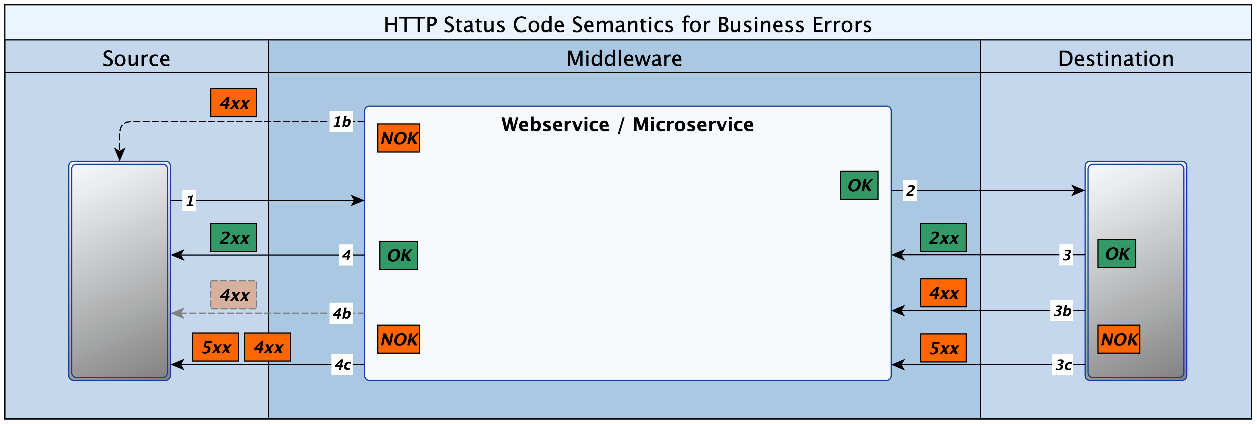
It is useful to define what is meant by a technical error, to wit, any failure that occurs on account of the network, infrastructure, application code, or the basic structure of the message (headers, security or payload). There are two scenarios that are pertinent to this discussion. In the first, the FE sends an invalid request and the MW rejects it immediately, returning a 4xx error to the FE.
In the second, the FE sends a request, the MW accepts it and forwards same to the BE. The BE rejects the request with either a 4xx or 5xx. However, since the problem occurred in the hop between the MW and the BE, the MW remaps the error to a 5xx, which it returns to the FE. The remapping aligns correctly with the semantics of HTTP status code groups 4xx and 5xx, given that the MW is not a pass-through. See the diagram below for an illustration.
This may sound incorrect or misleading, however, in practical terms, any technical errors that occur after step 2 are most unlikely to have anything to do with the FE, given the functions performed by the MW. A 4xx would imply that the FE was at fault, and as such, the error details would be required for it to rectify the problem, whereas in this case those details would only make sense to the FE. There may be exceptions of course, but the approach is good for most cases.
But things start to creak a bit when business errors are encountered. Once again, it is pertinent to pause and define what constitutes a business error. In this context we refer to all errors that occur after the HTTP dialogue has completed successfully. This implies that the FE has sent a request to the MW, the MW has examined the request and passed it to the BE. The BE has in turn accepted the request without faulting any of the technical aspects: network, infrastructure, application code or message.
Having done some further processing of the message though, the BE identifies a problem with the request and reports this back to the MW. The problem here is that the HTTP status codes did not have business errors in mind during compilation. The status code groups (1xx, 2xx, 3xx, 4xx and 5xx) map very cleanly to genres of technical failures that could occur in the HTTP dialogue, at a technical level.
However, when it comes to business errors, there is no such clear mapping. Indeed, the only status codes that could, with some imagination, be leveraged for business errors are: 400, 409 or 422. The 400 code is a generic bad request; the 409 is an inconsistency of state, and the 422, introduced for WebDAV, indicates a semantic error. Neither is perfect, but even with all these, there would still be a huge shortfall. It is clear that there are far more than three kinds of business errors in the real world.
To further complicate matters, there are those that will assert that business errors are not errors in the sense implied by the HTTP status codes and should use the 2xx group, because, technically, there was no error. An alternative viewpoint emphasises the need to be aligned with the semantics of the HTTP status codes, and the fact that the MW is an active participant in the dialogue, as such, all errors, 4xx or 5xx ought to be mapped to a 5xx.
In a recent article, I spoke about ‘the fog of experience’, and how opinion and decisions become more nuanced as one travels down the paths and routes of our dynamic and ever evolving technological landscape. This is one of those where the answer is not without contention and some subjectivity. It is likely that various architects and organisations may differ on approach, but in each context, the opinions and final decision will be informed by knowledge and a pragmatic search and compromise on progress and value.
In my current context, the consensus is to accept the limitations of the HTTP Status codes and the fact that they are not about to change. However, standards and consistency are important to quality and velocity in an Agile and product-centric service model. For this reason, the decision was to recommend that all BEs capture business errors using the 422 HTTP status code. All such errors are to be accompanied by a payload that describes the business error, and optionally, any details that could help the FE to rectify it.
I still remember the early days when I first started out in tech. All answers were apparent and hardly was the ink dry on the request, and I was already delivering pieces of the solution. It was a kind of “Agile”; quick, and invariably, MVP. The success factors for me were essentially the functional aspects. Value was perceived from a tech perspective.
These days, so many answers are qualified, nuanced, and accompanied by caveats. Almost nothing is clear and certain. I have discovered that value is the prerogative of the customer, and he/she expresses it in subjective terms. However, the customer is often not the only important stakeholder, and one has to address all the concerns of key stakeholders to deliver a successful service. The matrix of concerns, constraints, opportunities, etc. is a hazy mesh that takes patience, knowledge, imagination and tact to navigate.
Oh, for the halcyon rookie days, of operating below the radar of key stakeholders, architectural governance, and budget holders! For certainty and technical purity, for the stream of tactical solutions, and the buzz/hit of seeing “it” work! I still remember one moment of amazement, when a visiting consultant pointed out to me that the collection of MVPs I had laboured over for the last two years was actually a mini ERP. Those were some memorable years, in London, Edinburgh and Southampton. It was a lot of adrenalin, noise, banter, late nights, early mornings, intense work and much fun.
I now work mainly in the integration & solution architect scopes, synthesising services from business, architectural and technical inputs. Constantly scanning for opportunities to drive innovation, efficiency and competitiveness, while also reducing complexity, cost and TTM. In addition to the requisite technical and business knowledge, my role involves tact++, listening++, politics, psychology, emotional intelligence, and social strategy. It is not a straight line, there are no easy answers, there is little fizz, and you do not enjoy a fiat in any context.
Neither do I ever deliver anything alone. I always work with others, no one works for me, but rather with me: hierarchies can oft-times be an impediment. I depend on others to implement, provide or revise funding, change scope, grant a dispensation, review a requirement, move a date, or compromise in one way or another, to advance the delivery of solutions, and value to our customers. Customers are the ones that pay for our activity, and it is key that we understand their perception of value in order to consistently deliver services that they are willing to pay for.
The customer is king! But KYC cannot always be gleaned from the organogram or reading through the requirements. What may be right for one customer with a tight and close market window might be an unacceptable hack for another. The solution that was gladly embraced by customer-A in Q3 of this financial year, when revenue was trending up, could be flatly rejected in Q1 when corrections reveal shortfalls. Over time, one does gain knowledge and one does build trust, and all this widens the scope of influence. However, with such a wide matrix of interdependencies, the role is always challenging and unpredictable.
All said and done, it is still very interesting and rewarding work. It is a journey of discovery, of self and others; of building relationships and trust; of learning from failures and successes; of growing in patience and perception, and of seeing the sometimes hard-to-perceive positive impact of changes one helped to nurture. And “Yes, it is a good life, ‘Henry’“.
Security in an interconnected, always-on (24*7), virtualised, digital world is important. As more of our IT infrastructure moves to the Cloud, proactively seeking and blocking emerging security gaps becomes a continuous activity (BAU).
AWS and Kubernetes are leaders in the new paradigm of abstracted infrastructure – Cloud, datacentre on on-premise. Both have their own evolving security arrangements. For role-based access control (RBAC), AWS uses the IAM primarily, while Kubernetes (K8s) uses a combination of Roles and Role Bindings. The primary RBAC intersection point between these two has been the node/virtual-machine (EC2).
The Problem
In a simple world, privileges assigned to the underlying AWS node are inherited by the K8s Pods running on the node. This works perfectly when there is a one-to-one mapping between the client of K8s and the consumer of the AWS node. Specifically; the same entity owns the K8s cluster and the AWS node on which it runs. Security is intact, irrespective of the number of K8s Pods on the AWS node. However, misalignment occurs when K8s shares the same node among two or more clients – often referred to as multi-tenant mode. A potential for a security breach emerges.
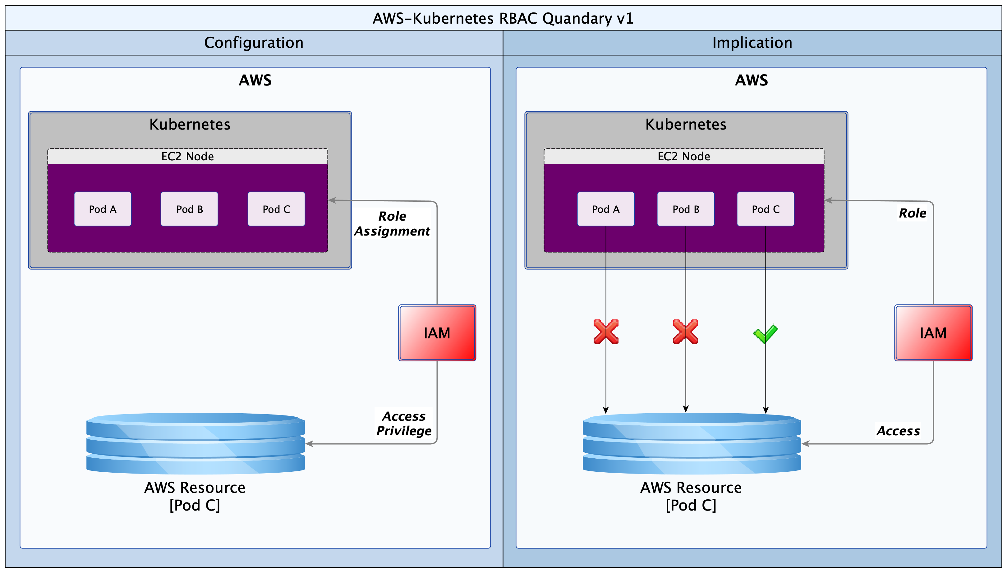
Imagine a scenario in which there are three K8s Pods (A, B & C) running on a single AWS node. Each Pod runs a service that belongs to a different customer/client. Pod A belongs to client-A, Pod B belongs to client-B and Pod-C belongs to client-C. Files needed by each client are stored on S3 buckets in AWS, and each client has responsibility to arrange for their own S3 bucket. However, client-C is the only one that has managed to provision an S3 bucket at the time of deployment. Ordinarily, Pod A and B should never access the resource(s) provided strictly for Pod C. But if they do, nothing stops them! The diagram below provides a useful illustration.
Historically, in IAM, access privileges to the resource for Pod C will have been given to the node hosting Pods A, B and C. The EC2 node would have an Instance Profile defined, and a Role will be attached to the Instance Profile, giving it those privileges. The unexpected consequence however is that Pods A and B also inherit the privilege from the host node. Pod C’s resources would therefore be accessible to any other Pod (client) running on that node. This obviously is not acceptable for a multi-tenant K8s cluster.
Solutions
The great thing about the Open Source community is that problems are attacked, and often solved, almost as soon as they are articulated. Two open source products emerged to close this security gap: Kube2IAM (2016) and KIAM (2017). Some time later, AWS introduced a solution; “IAM for Service Accounts”. However, the AWS solution only works with their EKS service. All three solutions make it possible to control access from K8s Pods to AWS resources.
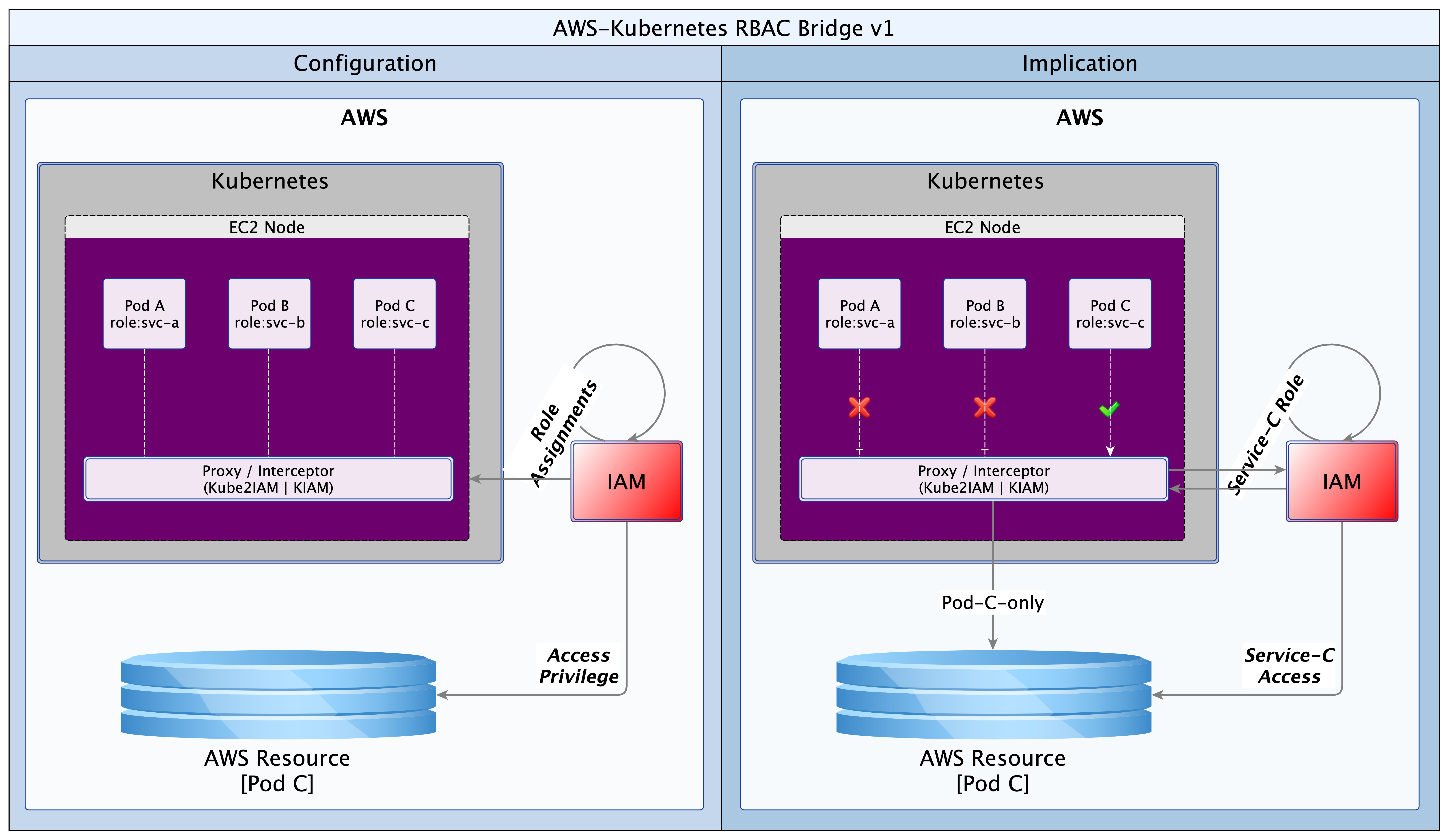
I will not discuss the AWS solution as it is proprietary and closely tied to their EKS offering. Neither will I examine KIAM as the solution has been abandoned by the developers. This leaves us with the forerunner: Kube2IAM. Kube2IAM deploys a K8s DaemonSet in the K8s cluster. By default, one Kube2IAM Pod is deployed to each worker node in the cluster. The Kube2IAM instance running on each node intercepts requests to the AWS metadata service URL (http://169.254.169.254). It then provides a response according the the IAM role assignments, as well as the annotations on the Pod calling the service. The diagram below provides a useful illustration.
With this simple solution by Kube2IAM, the exclusive role assignment to Pod C is respected by K8s. Deliberate or inadvertent requests by Pod A or B are blocked by Kube2IAM.
Here is how it works. When a Pod makes a request for AWS resources, it will make a call to the AWS metadata service URL. Kube2IAM hijacks the call (iptables reroute) and performs an inspection to see what the appropriate response should be. It checks if there are any appropriate RBAC annotations on the Pod making the request. If there are none, Kube2IAM serves up the default privilege set. These will be the privileges defined for the EC2 Instance Profile. However, if the Pod has a role annotation, it will be given the privileges defined in the matching AWS role.
Hands-on
In the example that follows, we will deploy two Pods; one with annotations (annotated) and another without (vanilla). We will use two AWS roles. The read-only role will have access to one S3 bucket only. The other read+write role will have read access to 2 buckets and read+write access to one bucket. The read-only role will be attached to the EC2 Instance Profile for the K8s worker node. The read+write role be standalone, but it will be extended to trust the read-only role. This sets the stage for Kube2IAM to discriminate between requests, giving read and/or write access to our Pods, as appropriate. In our example, the annotated Pod will be able to write one bucket and read two buckets, while the vanilla Pod will only be able to read one bucket.
The implementation artefacts can be downloaded from GitHub (use this link). I have put together what I think is a simple, and perhaps more explicit set of instructions below. Follow them step-by-step and you should end up with a working RBAC bridge using Kube2IAM. I guess one could write a script that automates all of these steps, but that is a task for another day, or perhaps someone else.
Process
Create a policy (nettech-s3-read-only); use the file nettech-ec2-instance-profile.json for the policy definition/contents
Create a role (nettech-s3-read-only); the role should refer to the policy in step #1
Create an EC2 instance profile (nettech-instance-profile) for the AWS node(s); the instance profile should refer to the role you defined in step #2, forming a chain: nettech-instance-profile==>nettech-s3-read-only(role)==>nettech-s3-read-only(policy).
Use the following aws-cli commands:
aws iam create-instance-profile –instance-profile-name nettech-instance-profile
aws iam add-role-to-instance-profile –instance-profile-name nettech-instance-profile –role-name nettech-s3-read-only
Create a second read+write S3 policy and role (nettech-s3-read-write). Use the file nettech-s3-read-write.json for the policy definition/contents
Extend the trust relationship on the read+write S3 role such that it can be assumed by the read-only role, forming a link: nettech-s3-read-write(role)<==trust==nettech-s3-read-only(role).
In IAM console, select the read+write role
Select the “Trust relationships” tab, and then click on the “Edit trust relationships” button
In the new window that opens, add the contents of the file nettech-s3-read-write-trust-relationship.json to the existing definition/contents
Make sure to update the AWS account Id (01234567890) to your own
Click on “Update Trust Policy” to save your changes
Deploy or assign a worker node in your K8s (Rancher/Kops/..) cluster
Configure or update the worker node to reference the EC2 Instance Profile (nettech-instance-profile) from step #3
aws ec2 associate-iam-instance-profile –iam-instance-profile nettech-instance-profile –instance-id xxxxxxxxxx # replace xxxx with your instance Id, or use the AWS GUI to attach it
Deploy Nginx vanilla and annotated (K8s Deployments). Use the file nginx-deployment.yaml from Rancher UI or kubectl on the command line
Install aws-cli in each of the Nginx instances – Use the following commands (Linux):
Verify that the host node has read access to the “nettech-helm-test” bucket, according to the EC2 profile from step #3. Connect to the host node (via Rancher UI or SSH) and run the aws s3 ls command.
aws s3 ls nettech-helm-test
Verify that both Pods have read access to the “nettech-helm-test” bucket. Connect to each Pod (via Rancher UI or kubectl) and run an aws s3 ls
aws s3 ls nettech-helm-test
Create/deploy ClusterRole & ClusterRoleBinding for the service account to be used by Kube2IAM. Use the file clusterRoleAndBinding.yaml
Deploy Kube2IAM (K8s DaemonSet), with debugging enabled. Use the file kube2IAM-daemonSet.yaml
Connect to the host node and access the command line. Check that only one IPTables rule exists on the worker node (for AWS metadata IP). Delete any duplicates to avoid confusing errors. This may happen if you redeploy the Kube2IAM Daemonset.
sudo iptables -t nat -S PREROUTING | grep 169.254.169.254 # list all entries
sudo iptables -t nat -D PREROUTING -d 169.254.169.254/32 -i docker0 -p tcp -m tcp –dport 80 -j DNAT –to-destination 10.43.0.1:8282 # delete any duplicates
NB:(docker0) is the network interface, (10.43.0.1) is the IP address of the node/host, and (8282) is the Kube2IAM port
Test the Nginx instances again
Verify that the host node still only has read access to “nettech-helm-test”, as defined as a default in the EC2 Profile role (nettech-s3-read-only)
Verify that the vanilla Nginx Deployment still only has read access to “nettech-helm-test”, as defined as a default in the EC2 Profile role (nettech-s3-read-only)
Verify that the annotated Nginx Deployment now has read access to “lanre.k8s.dev” and “nettech-helm-test” as well as read+write access to “lanre.k8s.dev”
Conclusion
An RBAC bridge of some sort is a necessity for all multi-tenant K8s clusters running on virtualised infrastructure such as AWS, Azure, GCP and others. Kube2IAM provides an effective solution for the AWS platform. This article identifies the issue that Kube2IAM resolves and shows a very simple, sandbox implementation. The article should serve as quick-start guide that is easy to grasp and quick to implement.
We live in a rapidly evolving technology environment. Kube2IAM has set a very sound foundation, but as always, there is always room for improvement; and I say that with all humility and respect for the developers. KIAM came up with a cacheing service to reduce latency and improve scalability, unfortunately, that solution is no longer being evolved. One would like to see similar functionality in Kube2IAM. One other improvement would be to move the annotations out of the Pod and into K8s roles. The preference being roles defined outside the namespace of the beneficiary Pod. This will reduce the attack surface for malicious code that might attempt a brute-force attack to find AWS roles that can be exploited.
Many thanks to Jerome Touffe-Blin @jtblin and his team for creating this ever-so-useful open-souce utility.
The Cloud may not be in-your-face. But it is pervasive, and gradually taking over many aspects of our traditional IT systems. Companies are not yet making wholesale transitions from existing data-centres and on-premise assets to Cloud. However, when infrastructure reviews occur, whether to upgrade or add new resources, the Cloud beckons. Questions about total cost of ownership (TCO), scalability, time-to-market, etc will influence decision makers. For each one of these, the Cloud offers a compelling alternative. It is likely that in the next two decades, only a few companies will still maintain their infrastructure on premise.
Let us assume then that ACME plc has made a decision. Business has been persuaded, either by hype or fundamentals, that the Cloud is the strategic target. Architectural leadership has been mobilised and a decision taken to draw up a roadmap for Cloud adoption. What next? In this article, we look at four primary considerations that architects must carefully examine when migrating to the Cloud. These are: sizing, failover, scaling and access. Everything else builds on the foundation that is synthesised from these four dimensions.
Sizing: What Specification of Infrastructure Should be Provisioned
Statistics are invaluable. Node sizing should be empathetic to existing use profile. It may be okay to guess at first, but it saves so much time to know in advance. For each Cloud instance, the node(s) provisioned should be selected to meet latency and throughput required to support 120% of anticipated production load. The sizing could be either singular or plural. Singular, as in one node with enough capacity to bear all load; or plural, i.e. a number of nodes that can, between them, satisfy demand. But the baseline should exceed the present need.
Resizing in the Cloud may be quick and easy, but the decision making might not be so. If in doubt, over-provision. It is easy to downsize later, and the organisation avoids the risk of loss of business due to performance or availability problems. Default sizing is simple, i.e. geography localised and singular. But there could be exceptional scenarios where geographic distribution must be combined with plural sizing. More about that later.
Failover: How is System Failure Mitigated
Given proper sizing, as above, the next dimension to consider is failure and recovery. If or when a properly sized machine fails; what happens next? Let’s take the simple approach first and we will revisit this later. There should be a distribution of node(s) across Cloud locations, so that the failure of one node does not result in service unavailability. Service recovery should occur in a different Cloud location. This reduces the likelihood of contagion from the original failure location while maintaining service continuity. An interesting aspect of failure management is implicit resilience, i.e. what measure of interuption can our infrastructure handle?
The complement of the nodes that provide a service across Cloud location(s) is a resource group. The group resilience is the count of simultaneous failures that can be managed while maintaining SLAs. The higher the count, the larger the number of nodes and Cloud locations involved. Resiliency has a price tag though. More machines (virtual) will multiply cost and increase the percentage of idle/redundant resources in the Cloud platform.
Scaling: How are Additional Resources Provisioned
As resource demand grows organically, or due to unexpected spikes, infrastructure should respond, automagically! Traditionally, scaling was a bureaucractic and technical journey. With Cloud, scaling is merely a change of configuration. Where singular sizing has been used, another node of the same size could be added. This is horizontal scaling. Adding more nodes to singular sized nodes would multiply capacity. It is linear, but there is no guarantee of commensurate increase in demand or resource usage. There is an alternative design that is more efficient: programmatic vertical scaling. A simple algorithm can be applied to automatically scale resources; up or down, by a fraction rather than a multiple.
Cloud platforms record a raft of events about the resources deployed. Customers can tap in to these events to scale in response to demand. On AWS, CloudWatch alarms can trigger a Lambda function, which in turn effects a rolling upgrade on EC2 nodes; upscaling node size before autoscaling. By leveraging statistics for baseline sizing and monitoring demand, we can guarantee day zero availability and decent response in infrastructure provisioning. Increasing capacity as demand grows and shrinking it if or when spikes even out.
Access: How do Clients Connect to Cloud Services
The fourth dimension is access. As on-premise, so also with Cloud. There is no value in having resources that are locked away from everyone and everything. Our clients need access to our Cloud based services, so also partners involved in our service chain. Unless we are migrating all at once, it is likely that we will also need access to some on-premise infrastructure. Our design must provide the access paths and levels, as well as the constraints that keep authorised clients within band and everyone else out. To achieve this we would use such facilities as the Virtual Private Network (VPN), the load balancer, firewalls and others. Beyond the basics of who’s in and who’s out though, there is a service that we must provide to clients and partners.
The key here is to be simple and unobtrusive; placing minimal burdens on clients, partners and our applications/services.
By default we would use load balancers to decouple clients from service providers. Cloud load-balancers spread requests among available service providers. They are not geography specific and simplify access and security for clients and service provider. Our Cloud landscape is elegant and uncomplicated, with singular entry points for each service. One consideration could however force radical change to this default: Geographic Affinity (GA). Geographic affinity is a requirement to pin clients to a specific physical/geographical service provider. It could be zonal or regional. GA is often driven by regulatory, localisation, performance or security concerns.
But some GA drivers can be conflicting. For example, performance (latency sensitive applications) might be a problem where localisation (regional) is required. Invariably, GA tilts our architecture towards plurality of nodes and complications in managing performance and synchronisation of state. Architects must balance, sometimes conflicting, needs to avoid creating virtual silos in the Cloud.
Cloud Chaos
The Availability Index
So far we have been working forwards from an existing status quo to a target architecture. We have also adopted an exclusively technical perspective. What would be better is to take a business perspective. To approach our context top down. We should ask: what infrastructure is needed to support our business vision, now and into the near future? What level of availability is enough to provide service that exceeds client needs. In asking these questions, we encounter a new concept: “the Granularity of Perception”. This can be described as the number of microseconds, milliseconds, seconds, minutes, or more that impacts our service(s), as perceived by clients. Simply put: how slowly can we blink before our clients start to notice that our eyes have moved. As this number (granularity) increases, the required level of availability decreases. The table below provides a rough guide, with descriptions.
Availability Index
Description
1
Cluster enabled, auto recovery, no fail 24×7, latency intolerant, high-frequency, geography affinity
3
Cluster enabled, auto recovery, no fail 24×7, latency intolerant, medium frequency
5
Cluster enabled, auto failover, business hours, latency tolerant, low frequency
7
Non clustered, manual failover, business hours, latency tolerant, low frequency
The goal of architects should be to design a Cloud platform that delivers a granularity that is finer than the perception of clients. Using the table above as a guide, architects should play out scenarios with the service portfolio against each index. Starting with the least to the highest. Once the required availability index is determined, it should be relatively easy to identify the dimensions to support it.
Conclusion
As organisations embark on the journey of digital transformation, one early change is often Cloud adoption. This is because the Cloud provides a catalysing medium in which many solutions are easier and quicker to provision. In moving from on-premise/data-centre resources to the Cloud, architects must resist the temptation to simply lift-and-shift. Rather, the digital transformation journey should re-examine the fitness-for-purpose of existing solutions, platforms and infrastructure. There is a famous quote by Jack Welch, former CEO of General Electric. He said, “If the rate of change on the outside exceeds the rate of change on the inside, then the end is near.”. In a rapidly evolving globalised economy, business agility is becoming a precondition for survival.
The availability index is a simple, logical, technology-agnostic technique for conceptual reasoning about a Cloud landscape. Determination of the availability index helps to reveal shared profiles for similar subsystems. The profiles are logical and help estimate the resources required to support a genre of subsystem. Each logical profile can then be mapped to specific Cloud infrastructure and captured as customisable templates. The logical profiles provide architects with a starting point for solution designs. The infrastructure templates serve as a baseline for DevOps teams. Each artefact is likely to go through a number of evolutions. However, it is vital that both views are kept in sync at all times.
Organisations that leverage this approach will see a marked improvement in the consistency of infrastructure designs. Other benefits include faster turnaround of solutions, and systems that balance technical capability with business needs and aspirations. Architecture teams that leverage the availability index position their organisations for superior agility and competitiveness in the global economy.
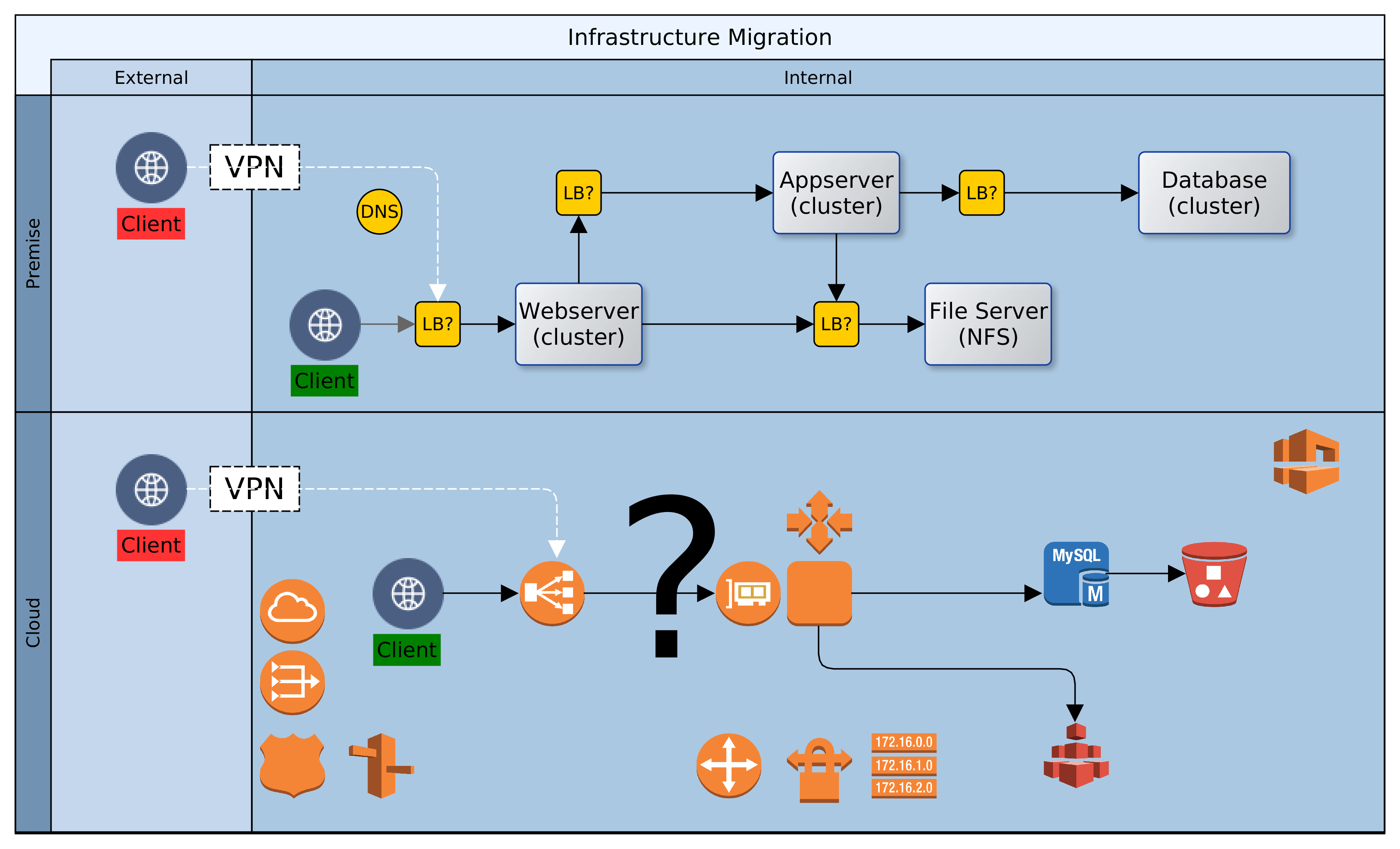
In a previous article, “One thousand servers, start with one click”, I described the design and implementation of a simple hybrid-Cloud infrastructure. The view was from a high level, and I intend, God willing, to delve into the detail in a later instalment. Before that though, I wanted to touch on the subject of hybrid Cloud security, briefly.
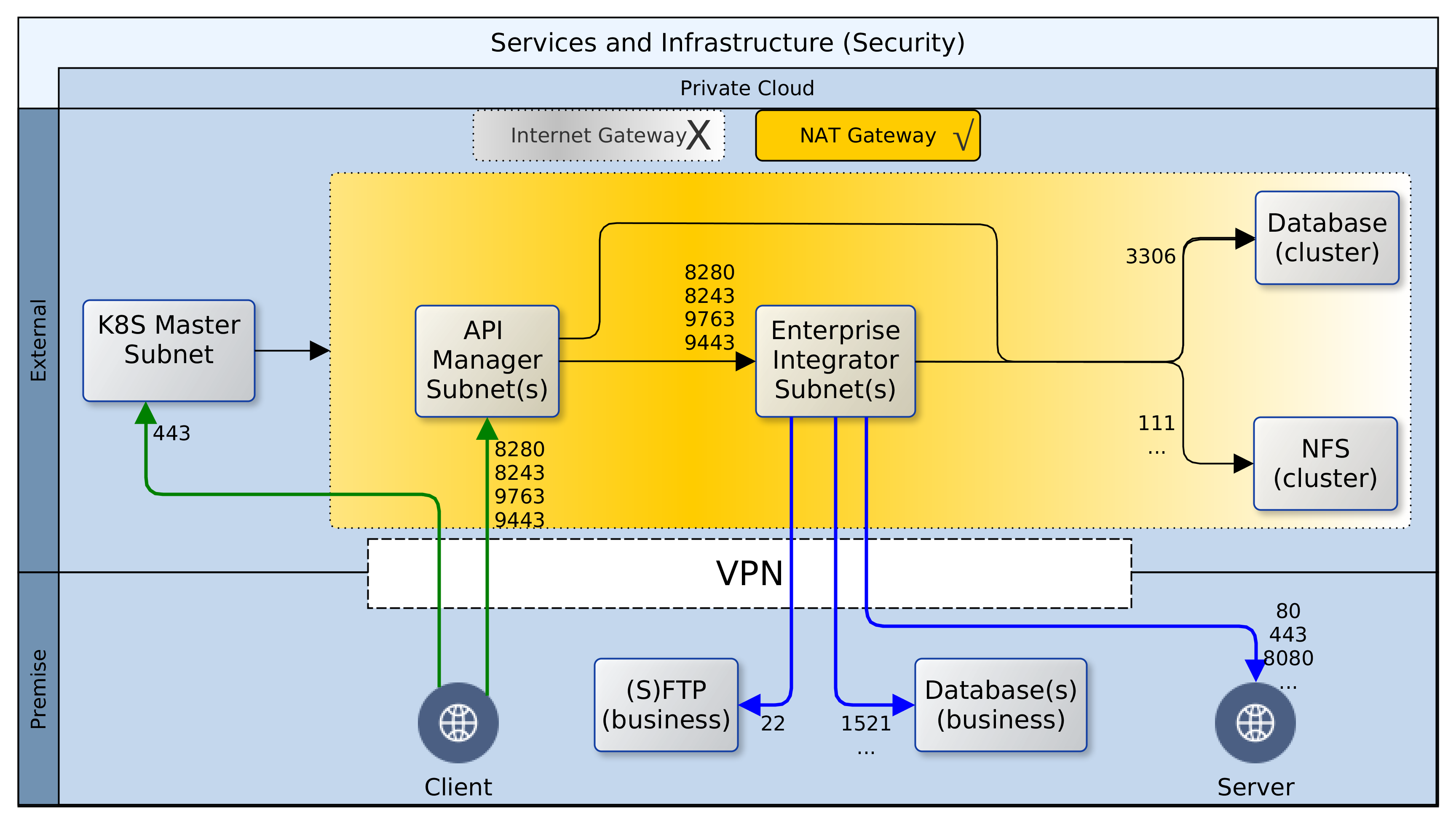
Having deployed resources in a private Cloud and on-premise, certain precautions should be taken to secure the perimeter and the green zone inside the two networks – Cloud and premise. The diagram above paints the big picture. It shows how, based on AWS security recommendations, minimal access/privilege is granted to each resource in the networks. The focus here is on machine access, which is about the lowest level of security. I will not delve into AWS policies, VPN configuration or on-premise firewall rules, as these are not black-and-white and the detail involved does not fit in with the goal for this article.
Here goes! Reading the diagram and translating to words:
It is convenient to use the Internet Gateway (public router) of your Cloud provider during development. Once you are done with prototyping and debugging, it should be disabled or removed. Switch to a NAT gateway (egress only router) instead. Your servers can still connect to the outside world for patches, updates, etc. but you can control what sites are accessible from your firewall. Switching to a NAT gateway also means that opportunist snoopers are kept firmly out.
Open up port 443 for your Kubernetes (K8S) master node(s) and close all others – your cluster can even survive without the master node, so don’t by shy, lock it down. Should the need arise, it is easy to temporarily change Cloud and premise firewall rules to open up port 22 (SSH) or others to investigate or resolve issues. Master nodes in K8S master subnet should have access to all subnets within the cluster, but this does not include known service ports for the servers or databases.
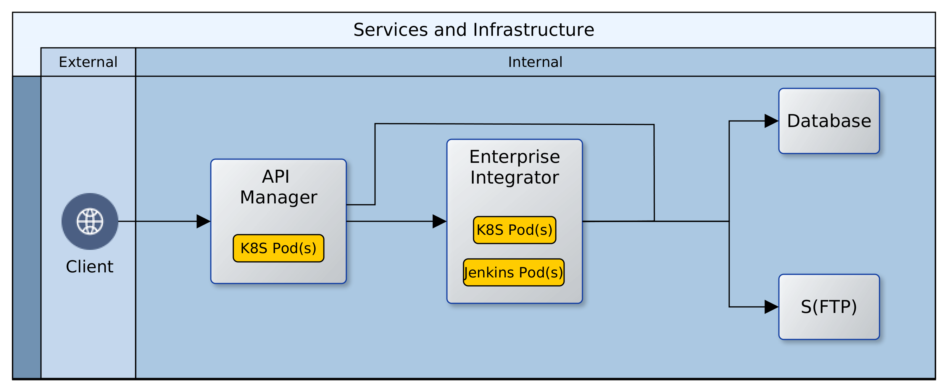
While your ESB/EI will have several reusable/shared artefacts, the only one that are of interest to your clients (partners) are the API and PROXY services. For each one of these services, a Swagger definition should be created and imported into the API Manager (APIM). All clients should gain access to the ESB/EI only through the interfaces defined in the APIM, which can be constrained by security policies and monitored for analytics. Therefore, the known service access ports should be open to clients on the APIM, and as with the K8S master, all other ports should be locked down.
Access to the known service ports on the ESB/EI should be limited to the APIM subnet(s) only, all other ports should be closed.
The Jenkins CI/CD containers are also deployed to the same nodes as the ESB/EI servers, but they fall under different constraints. Ideally, the Jenkins server should be closed off completely to access from clients. It can be correctly configured to automatically run scheduled and ad-hoc jobs without supervision. If this is a challenge, the service access port should be kept open, but only to access from within the VPN, ideally, a jump-box.
Access to the cluster databases should be limited to the APIM and ESB/EI subnets only, and further restricted to known service ports – 3306 or other configured port.
Access to the cluster NFS should be limited to the APIM, ESB/EI, and K8S-master subnets only, and further restricted to known service ports – 111, 1110, 2049, etc., or others as configured.
On-premise firewall rules should be configured to allow access to SFTP, database, application and web-servers from the ESB/EI server using their private IP addresses over the VPN.
Wherever possible, all ingress traffic to the private Cloud should flow through the on-premise firewall and the VPN. One great benefit of this approach is that it limits exposure; there are fewer gateways to defend. There are costs though. Firstly, higher latencies are incurred for circuitous routing via the VPN rather than direct/faster routing through Cloud-provider gateways. Other costs include increased bandwidth usage on the VPN, additional load on DNS servers, maintenance of NAT records, and DNS synchronisation of dynamic changes to nodes within the cluster.
ADDENDUM: Except for SFTP between the ESB/EI server and on-premise SFTP servers, SSH/port-22 access should be disabled. The Cloud infrastructure should be an on-demand, code-driven, pre-packaged environment; created and destroyed as and when needed.
And that’s all folks! Once again, this is not an exhaustive coverage on all the aspects of security required for this hybrid-Cloud. It is rather a quick run-through of the foundational provisions. The aim being to identify a few key provision that can be deployed very quickly and guarantee a good level of protection on day one. All of this builds on a principle adopted from AWS best practise. The principle states that AWS is responsible for the security of the Cloud while end-users are responsible for security in the Cloud. The end-user responsibility of Cloud security begins with another principle: access by least privileges. This means that for a given task, the minimum privileges should be granted to the most restricted community to which one or more parties (man or machine) is granted membership.
The arrival of Cloud providers and Infrastructure-as-a-Service (IaaS) has opened up options and possibilities for solution architects. Our company is working with a client on a major transformation initiative. Leveraging Cloud IaaS and open-source integration platforms, together we have explored options, built competence, and delivered incremental solutions while keeping costs to a minimum. Without Cloud IaaS and open-source this freedom of expression in solution architecture would have been impossible. Just imagine justifying a multi-tier, multi-server solution to the CFO when one of the key drivers has been cost control!
The Basic Idea
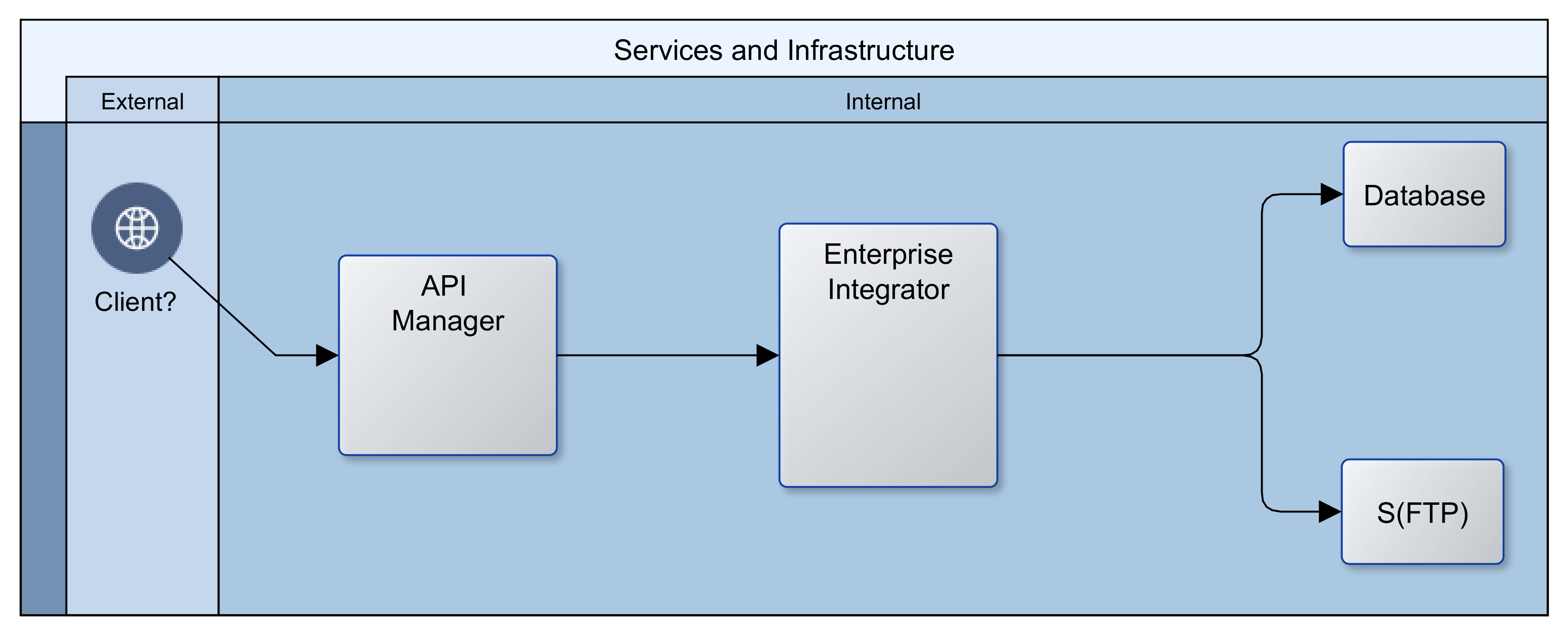
In its most primitive expression, our client wanted a public Application Program Interface (API) layer to abstract access to an Integration layer, which in turn connected with all their internal repositories and partner systems to provide services. The image that follows provides an illustration. It appears quite straightforward and simple.
The API layer provides a simple Representation State Transfer (REST) interface as well as security. It also maintains logs that can be analysed for insights into client behaviour and the usage/performance of services. The Integration layer serves as an Enterprise Service Bus (ESB), connecting to databases, FTP and/or file servers, as well as internal and partner web services. In addition, it manages the interactions between all participating systems in the enterprise and ensures that valuable services are made available to the API layer.
Enter Cloud (AWS/Azure) and Open Source (WSO2)
The traditional route would have been to procure/secure access to servers in a data-centre or in-house server-room and buy licenses from a vendor. That would have meant a lead time of several weeks or months, to negotiate the price of licenses and consultancy, arrange for servers and networking, and to secure and disburse requisite financing. With Cloud and open-source software, upfront costs were near-zero. The greatest resource demand was the effort required to architect the Cloud infrastructure and to create the code to build, populate and operate it.
Building the Foundation
There were many options for building the networking and computing instances. We chose Kubernetes. Kubernetes is well established and provides abstractions that make it easy to switch Cloud providers. Using the analogy of a house for illustration; Kubernetes builds the shell of the house, setting up the rooms, corridors, and spaces for windows and doors. It keeps a record of each component, and notifies all other components if there has been a change to any one of them. In our use case, Kubernetes creates a private network in the Cloud (cluster), adds compute-instances, load-balancers, firewalls, subnets, DHCP servers, DNS servers, etc. Kubernetes also provides a dynamic registry of all these components that is kept up to date with any changes in real time.
The First Change: Redundancy
In the past, vertical scaling with large singleton servers was standard. These days, horizontal scaling with smaller machines (compute instances) that adjust to changing needs is the norm. This new approach also provides fail safety. If one machine fails, there will be other(s) to take up the load. Fortunately this is a core feature of Kubernetes. The cluster monitors itself to ensure that all the declared components are kept alive. If/when a component fails, the management services within the cluster ensure that it is replaced with an identical component. For this reason, rather than have one instance of each component, two or more are created and maintained.
The Second Change: Dynamic Delivery
We could have chosen to install all of our technology stack (software) on each compute instance on creation. That would be slow though, and it could mean that the instances would need to be restarted or swapped-out more often as memory and/or disk performance degrade. Instead of that, we used Docker to build Containers that are delivered to the instances. The Docker Containers borrow memory, CPU and other resources from the compute instance at the point of deployment. Containers can be swapped in and out, and multiple Containers can be run on the same compute instance. When a Container is stopped or removed, the block of borrowed resources are returned to the compute instance. A Container can be likened to a prefabricated bathroom; it is built offsite and plumbed in at delivery. Unlike a technology stack that is built from scratch over minutes or hours, a Container is usually ready for access within a few seconds/minutes of its deployment.
Implicit Change: Clustering
When more than one instance of a genre component is running at the same time, the complement of all is referred to as a cluster. Components running in a cluster have peculiar needs; one of which is the sharing of state (status). State is a snapshot of the world from the computer’s perspective. In a cluster, all component instances must share the same configuration and operate on the same data always. To facilitate this, we introduced two repositories. A Network File System (NFS) for sharing configuration details, and a database for sharing operational data. Kubernetes does not create these resources. We used Terraform, another abstraction technology, to create the NFS and a replicated multi-zone database. Terraform creates these in two private subnets within the private network created by Kubernetes. Having created the NFS and database though, there was a need to configure and populate them with necessary data upfront. While Terraform could be manhandled to achieve this, it is not really it’s raison detre. Another tool is more suited to operating at a fine detail on remote machines: Ansible. We created Ansible playbooks to configure users, directories and files on the NFS and to create instances, users and tables in the database.
Implicit Change: Discovery
The next challenge that our architecture threw up was discovery. Within our network, there was an API layer and an EI layer. In each of these layers, there could be several compute instances, and on each compute instance there could be one or more Docker Containers. Beyond the API and the EI layers, there were also databases and a network file system. How would clients or our platform gain access to our components, and how would the machines in one layer find those in another layer? The Kubernetes configuration includes ClusterIP services that provide a single DNS name that resolves to all the compute instances for a given component. For example, any API Container could be reached using a DNS name such as: cnt.api.example.com. Clients of our platform could therefore use a DNS name to connect to an API Container, and any API Container could likewise use a single DNS name to communicate with a Docker Container in the EI layer. Both the API and EI layers use a DNS name to communicate with the NFS and the database. The IP address of the underlying components might change, but the DNS name is constant for the life of the platform, giving ease of discovery and stability.
Tying it all Up
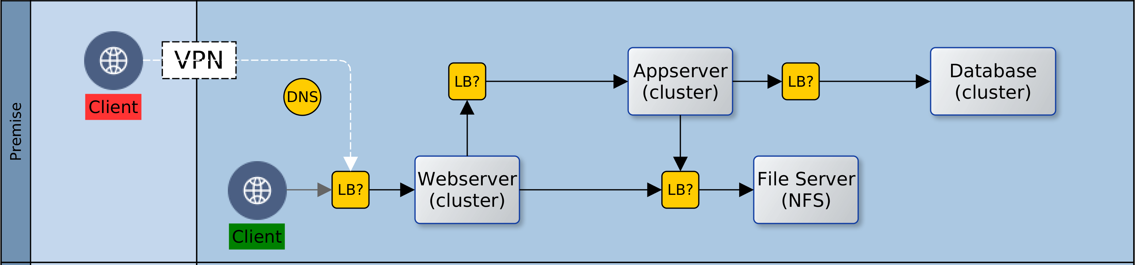
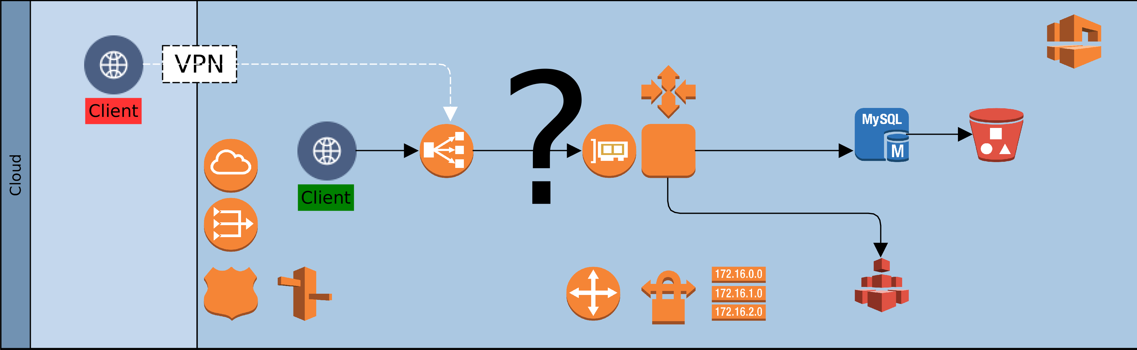
It is all well and good that the components in the Cloud are in place and can talk with each other. However, most of our operational systems are still on-premise; how do we join things up? We created a VPN connection between the network in the Cloud and our on-premise network and set up Firewall rules to allow access to and from the Cloud. The ClusterIP services were also revised to permanently maintain two static IP addresses. This makes it easy to integrate them with on-premise DNS servers and thereby open them up to access from clients. Below is an image that shows what it all looks like.
The Thousand Servers
All of these components, configurations, and customisations have been documented as scripts, configuration files and resources. The creation of a Cloud environment is reduced to running a script with two parameters: the name of the environment and the desired Cloud subnet. By integrating this script into an on-premise CI/CD server, it is now possible to spin up as many Cloud environments as we like; at the click of a button.
All this is quite high-level and simplified; in the next instalment (One Thousand Servers: Start with a Script), I intend to drop down to eye-level and throw up some of the details of how we implemented all of this. Watch this space for the activation of link above.
We all see the world from different perspectives, and the sum of perspectives help us to get a better/fuller understanding of our world. In this article, we share a perspective on engineering services for business. This perspective can be summarised as: Intelligent Laziness – strategies to achieve equal or better productivity with equal or less effort and minimal stress. To illustrate how we try to achieve this, we will use five metaphors:
When people think of factories, they imagine the primitive/simple product-focussed line that spews out large numbers of identical, low-value items. http://www.verbolt.co.za/company-home.htm
But there is another perspective; the advanced/composite service-focussed systems that create a few bespoke high-value units to specific customers. http://www.orangecountychoppers.com/
There are similarities, in that both are repetitive and they both transform inputs to outputs. But there are significant differences too. The primitive factory involves lower risk, and less complexity whilst the advanced factory multiplies risk due to composition and customisation. There is a direct relationship between value and complexity, and it is often the case that the advanced factory uses outputs from primitive factories.
But factories occur in software engineering too, and the underlying principles apply here too. Whereas it is common to talk of dichotomy in software engineering: is it a science or an art? Software factories do not suffer such ambiguity. For every factory, whether hardware or software, two principles always apply:
The outcomes are predictable
The process is repetitive
Careful study of any system reveals re-occurring things/trends the production of which can be achieved with the factory principles. This is equally true in a McDonalds restaurant as in a Rolls-Royce workshop. This is also true in software engineering, especially service engineering.
The Pattern
The re-occuring things/trends in a factory are patterns. The predictability of the output of a factory and the fidelity of repetition depend on patterns. Patterns are fundamental to factories. In a factory, there is a need to understand what is to be produced and the patterns that are involved in its production. Each pattern is a kind of template. Given certain input and application of the template, a given output is guaranteed. A factory is likely to involve mastery of one or more patterns, depending on the type of factory. Fewer patterns generally reflect superior understanding of the problem domain. However, some patterns go through special evolution (exaptation) and could become the focus of a factory in their own right.
The Framework
The collection of patterns required to create a given output can be described as a framework. A good analogy is a box of Lego. It is a composite of patterns, which can be put together to create the structure illustrated on the box/packaging. The framework identifies all requisite patterns for a given output, and usually in a given technical/business context. Each pattern in a framework form synergies and are known to be beneficial in the specified context; examples of frameworks include building regulations (hardware) or Oracle AIA (software).
The Process
Of course having all the pieces of a Lego is insufficient to construct the picture on the box. The process elevates the framework from static to dynamic. The process describes how the patterns in a framework are to be sequenced and aggregated in a way that delivers synergy and the best output. The framework is a snapshot, whereas the process describes a flow from conception to completion. For business services, the process is the first point where IT and business meet. The process shows how value can be created while hiding (abstracting) the taxonomy/ontology of patterns and the framework(s) employed.
How does all of this come together, especially in our daily lives as software engineers serving businesses? And how does this help our clients (the business) better compete? Join me in the next instalment where I will be looking at the benefits, business connection, and potential future impact.
In a previous article, I looked at how some metaphors can be used to understand the engineering of software (services). Of the five listed below, I introduced the first four.
Factory
Pattern
Framework
Process
Service
The first three have a clear technical focus; the fourth is a gateway between the technical world and the business world. The fifth though is where the business focus becomes paramount.
IT is an enabler – no one invests in technology for itself, rather it is for what IT can do for business. The service is the business perspective on the process. It focusses on how all those patterns and frameworks abstracted within those processes can be put to work for business. But even business is not without patterns! Every business operates in a sector, and belongs to a genre. For every business genre, there are certain must-have competencies common to all participants, as well as some differentiators that are peculiar to some players. The build up from our patterns to the processes must be honed to effectively serve out clients; the business, who themselves have clients: the buck-paying end-users.
The Service as Business Nexus
The reliability, efficiency and quality of our technical processes must feed into our business clients and aid their agility. A business that is supported by factories at different levels (pattern, framework, process) is more able to adapt to a changing environment. Such businesses are able to recombine solutions at different levels of granularity to address emerging needs.
It is vital to make a distinction between software-engineering per se and service-engineering. At the different levels of the vertical hierarchy of software, there are factories that have no alignment to any business whatsoever. They are simply technology enablers. The focus here is on services, i.e. software that is “client” driven. In a Service Oriented Architecture (SOA) there is an intrinsic/instinctive alignment to business. I go even further to speak of a “fundamentalist SOA“, characterised by the following principles:
Build Best
Owner-Agnostic
Interdependent Services
Service Ontology
Attritional Evolution
We should build on Steven Covey’s (The 7 habits of highly effective people) principle of interdependence and Steven Johnson’s (Where good ideas come from) ideas of next-adjacent, serendipity and exaptation. Everyone should not build everything. No one should build just for themselves. But let every output be seen as a target (service) for the genre or sector/industry rather than the department or the company.
There are significant benefits to this mindset:
Cheaper solutions: due to successful scaling of a few best patterns
Easier, Faster: due to extreme specialisation of the most successful patterns
Simpler Maintenance: due to deep understanding of the pathology of the patterns
Fewer Faults, Quicker Fixes: due to clear modularity/decomposition of the patterns
Better Scalability: due to to built-in fundamental qualities of patterns
More/Better Output: as patterns are re-composed at higher levels of abstraction
But these kind of solutions are themselves products of a new learning. This learning is focussed on the core nature of the problem rather than its specifics. It is meta-learning that looks for patterns in the problem domain and then maps each to a resolver in the solution domain. This Weltanschauung delivers, and it is an enabler for federation of output as seen in open-source software. It is a value well demonstrated in Amazon Web Services. Without this mindset, corporations like YouTube or DropBox would not have gotten off the ground. With it, the evolution of novice to expert is more likely to be successful and the duration of the transform is more predictable and much shorter. One expects that all this would also produce more of Jeff Bezos “work-life harmony” for those involved. As well as better and cheaper output for those buck-paying clients, at all levels!
Plus ça change … ?
Computers know nothing! Deep-blue would not know how to crawl out of a pond if it fell into one. But we can teach it to. We communicate with machines through patterns; the patterns represent an abstraction of our language and knowledge. The patterns help us to teach machines, and thereupon to delegate to them. Better abstraction means we can get more out of the machines. The patterns are our bridge to the nebulous machine world.
Increasing the variety and the speed at which we add abstractions will hasten the metamorphosis of ideas to reality. Each one extends our metaphorical bridge; from the machine end to the human end. As we do so, alterations to our present reality will emerge ever faster, as our most abstract ideas and desires are projected across bridge of abstraction into new and tangible experiences. The foundation of all this is and will be unavoidably linked to those principles that we started with earlier: the factory, pattern, framework, process, and service.
That is my (view point) perspective.


![[Hybrid] Cloud Infrastructure](https://blog.net-technologies.com/wp-content/uploads/2017/12/ExeterUni_CloudInfrastructure.03.png)
![[Hybrid] Cloud Infrastructure](http://blog.net-technologies.com/wp-content/uploads/2017/12/ExeterUni_CloudInfrastructure.03.png)